Toyota Tundra Service Manual: System Description
(a) The Controller Area Network (CAN) is a serial data communication system for real time application. It is a vehicle multiplex communication system which has a high communication speed and the ability to detect malfunctions.
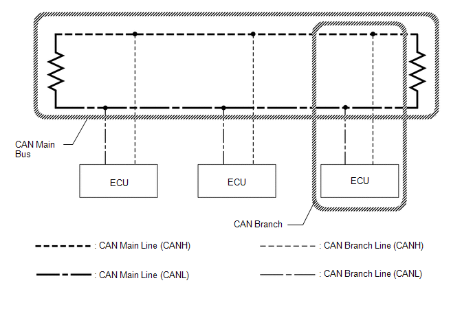
(b) Using the CANH and CANL bus lines as a pair, CAN communication is performed using a voltage differential. (A base voltage is applied to the pair of lines and a voltage differential is created when communicating.)
(c) Many ECUs or sensors installed to the vehicle operate by sharing information and communicating with each other.
(d) 2 resistors which are necessary for communication are used in a CAN bus main line.
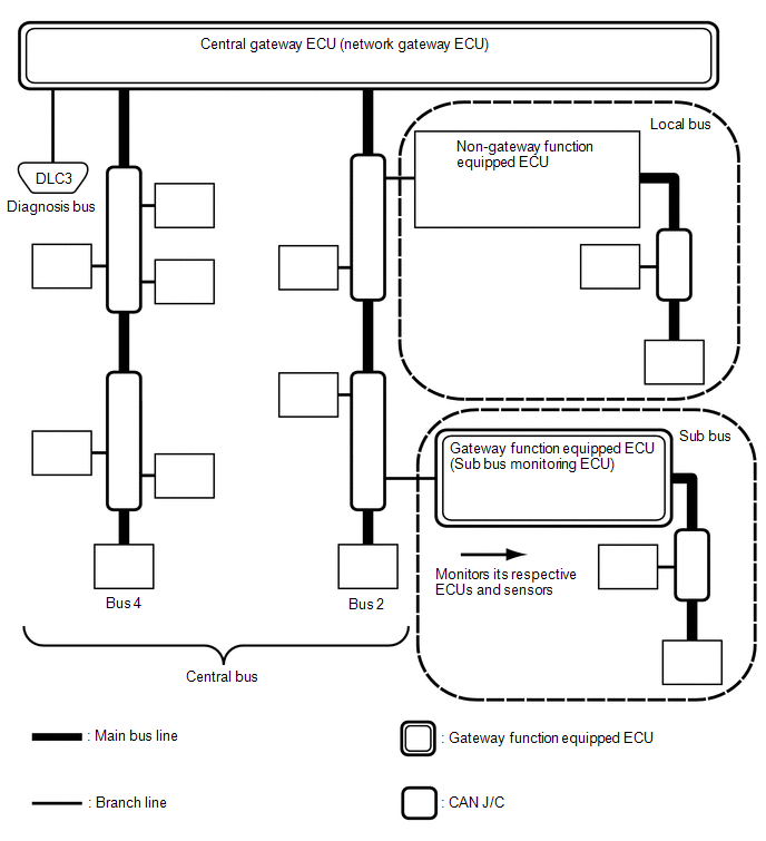
(1) The central bus is a generic name for multiple subordinate CAN bus lines on the central gateway ECU (network gateway ECU).
A bus is displayed as Bus on the «Communication Bus Check» screen of the Techstream.
(1) A sub bus is a bus that has a gateway function equipped ECU in order to communicate with the central bus and other sub buses.
- A sub bus is displayed as Sub bus on the «Communication Bus Check» screen of the Techstream.
- When Sub bus is selected on the «Communication Bus Check» screen, ECUs and sensors connected to non-CAN networks such as LIN may also be displayed in addition to the ECUs and sensors connected to sub buses in the CAN network.
(1) A local bus is a bus that does not have the ability to communicate with other buses. ECUs and sensors on a local bus can only communicate with other ECUs and sensors on the same bus.
Gateway function not equipped ECU is a generic name for ECUs not connected to the central gateway ECU (network gateway ECU) with a gateway function.
(1) A CAN junction connector is a connector that connects branch lines to a main bus.
(1) A main bus line is the wire harness that runs between the 2 terminating resistors of a bus.
(1) A branch line is a wire harness that connects an ECU or sensor to a main bus line.
(1) Terminating resistors which maintain a stable signal inside the CAN bus are installed. 2 resistors of 120 Ω each located at each end of the bus are necessary.
- except Diagnosis Bus: 2 resistors of 120 Ω each located at each end of the bus are necessary.
- for Diagnosis Bus: 1 resistor of 60 Ω located at end of the bus are necessary.
Toyota Tundra Service Manual: Lost Communication with «Door Control Module A» (U0199)
There is no communication from the outer mirror control ECU assembly LH.
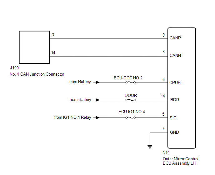
- Outer mirror control ECU assembly LH CAN branch wire or connector
- Power source or inside of outer mirror control ECU assembly LH
- Outer mirror control ECU assembly LH ground circuit
- Outer mirror control ECU assembly LH
CAUTION / NOTICE / HINT
When performing the confirmation driving pattern, obey all speed limits and traffic laws.
- Because the order of diagnosis is important to allow correct diagnosis, make sure to begin troubleshooting using How to Proceed with Troubleshooting when CAN communication system related DTCs are output. Click here
- Before measuring the resistance of the CAN bus, turn the ignition switch off and leave the vehicle for 1 minute or more without operating the key or any switches, or opening or closing the doors. After that, disconnect the cable from the negative (-) battery terminal and leave the vehicle for 1 minute or more before measuring the resistance.
- After turning the ignition switch off, waiting time may be required before disconnecting the cable from the negative (-) battery terminal. Therefore, make sure to read the disconnecting the cable from the negative (-) battery terminal notices before proceeding with work. Click here
- Some parts must be initialized and set when replacing or removing and installing parts. Click here
- After performing repairs, perform the DTC check procedure and confirm that the DTCs are not output again. DTC check procedure: Turn the ignition switch to ON and wait for 1 minute or more. Then operate the suspected malfunctioning system and drive the vehicle at 60 km/h (37 mph) or more for 5 minutes or more.
- After the repair, perform the CAN bus check and check that all the ECUs and sensors connected to the CAN communication system are displayed as normal. Click here
- Inspect the fuses for circuits related to this system before performing the following procedure.
- Before disconnecting related connectors for inspection, push in on each connector body to check that the connector is not loose or disconnected.
- When a connector is disconnected, check that the terminals and connector body are not cracked, deformed or corroded.
If DTC U1002 is output from Gateway of the main body ECU (multiplex network body ECU), this indicates a sub bus 1 malfunction. Troubleshoot for DTC U1002 and check for malfunctions in sub bus 1.
DTC U1002 is not output from main body ECU (multiplex network body ECU).
DTC U1002 is output from main body ECU (multiplex network body ECU).
GO TO DIAGNOSIS PROCEDURE INDICATED BY OUTPUT DTC
CHECK FOR OPEN IN CAN BUS WIRE (OUTER MIRROR CONTROL ECU ASSEMBLY LH CAN BRANCH WIRE)
(a) Disconnect the cable from the negative (-) battery terminal.
(b) Disconnect the outer mirror control ECU assembly LH connector.
Front view of wire harness connector
(to Outer Mirror Control ECU Assembly LH)
(c) Measure the resistance according to the value(s) in the table below.
Cable disconnected from negative (-) battery terminal
REPAIR OR REPLACE CAN BRANCH WIRE OR CONNECTOR
CHECK HARNESS AND CONNECTOR (POWER SOURCE CIRCUIT)
(a) Measure the resistance according to the value(s) in the table below.
Cable disconnected from negative (-) battery terminal
Front view of wire harness connector
(to Outer Mirror Control ECU Assembly LH)
(b) Reconnect the cable to the negative (-) battery terminal.
When connecting the cable, some systems need to be initialized after the cable is reconnected.
(c) Measure the voltage according to the value(s) in the table below.
Toyota Tundra Service Manual: Lost Communication with «Door Control Module B» (U0200)
There is no communication from the outer mirror control ECU assembly RH.
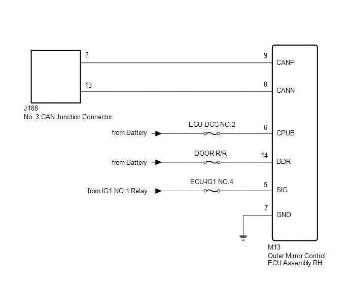
- Outer mirror control ECU assembly RH CAN branch wire or connector
- Power source or inside of outer mirror control ECU assembly RH
- Outer mirror control ECU assembly RH ground circuit
- Outer mirror control ECU assembly RH
CAUTION / NOTICE / HINT
When performing the confirmation driving pattern, obey all speed limits and traffic laws.
- Because the order of diagnosis is important to allow correct diagnosis, make sure to begin troubleshooting using How to Proceed with Troubleshooting when CAN communication system related DTCs are output. Click here
- Before measuring the resistance of the CAN bus, turn the ignition switch off and leave the vehicle for 1 minute or more without operating the key or any switches, or opening or closing the doors. After that, disconnect the cable from the negative (-) battery terminal and leave the vehicle for 1 minute or more before measuring the resistance.
- After turning the ignition switch off, waiting time may be required before disconnecting the cable from the negative (-) battery terminal. Therefore, make sure to read the disconnecting the cable from the negative (-) battery terminal notices before proceeding with work. Click here
- Some parts must be initialized and set when replacing or removing and installing parts. Click here
- After performing repairs, perform the DTC check procedure and confirm that the DTCs are not output again. DTC check procedure: Turn the ignition switch to ON and wait for 1 minute or more. Then operate the suspected malfunctioning system and drive the vehicle at 60 km/h (37 mph) or more for 5 minutes or more.
- After the repair, perform the CAN bus check and check that all the ECUs and sensors connected to the CAN communication system are displayed as normal. Click here
- Inspect the fuses for circuits related to this system before performing the following procedure.
- Before disconnecting related connectors for inspection, push in on each connector body to check that the connector is not loose or disconnected.
- When a connector is disconnected, check that the terminals and connector body are not cracked, deformed or corroded.
If DTC U1002 is output from Gateway of the main body ECU (multiplex network body ECU), this indicates a sub bus 1 malfunction. Troubleshoot for DTC U1002 and check for malfunctions in sub bus 1.
DTC U1002 is not output from main body ECU (multiplex network body ECU).
DTC U1002 is output from main body ECU (multiplex network body ECU).
GO TO DIAGNOSIS PROCEDURE INDICATED BY OUTPUT DTC
CHECK FOR OPEN IN CAN BUS WIRE (OUTER MIRROR CONTROL ECU ASSEMBLY RH BRANCH WIRE)
(a) Disconnect the cable from the negative (-) battery terminal.
(b) Disconnect the outer mirror control ECU assembly RH connector.
Front view of wire harness connector
(to Outer Mirror Control ECU Assembly RH)
(c) Measure the resistance according to the value(s) in the table below.
Cable disconnected from negative (-) battery terminal
REPAIR OR REPLACE CAN BRANCH WIRE OR CONNECTOR
CHECK HARNESS AND CONNECTOR (POWER SOURCE CIRCUIT)
(a) Measure the resistance according to the value(s) in the table below.
Cable disconnected from negative (-) battery terminal
Front view of wire harness connector
(to Outer Mirror Control ECU Assembly RH)
(b) Reconnect the cable to the negative (-) battery terminal.
When connecting the cable, some systems need to be initialized after the cable is reconnected.
(c) Measure the voltage according to the value(s) in the table below.
Toyota Tundra Service Manual: 4WD Control ECU Communication Stop Mode
When performing the confirmation driving pattern, obey all speed limits and traffic laws.
- Because the order of diagnosis is important to allow correct diagnosis, make sure to begin troubleshooting using How to Proceed with Troubleshooting when CAN communication system related DTCs are output. Click here
- Before measuring the resistance of the CAN bus, turn the ignition switch off and leave the vehicle for 1 minute or more without operating the key or any switches, or opening or closing the doors. After that, disconnect the cable from the negative (-) battery terminal and leave the vehicle for 1 minute or more before measuring the resistance.
- After turning the ignition switch off, waiting time may be required before disconnecting the cable from the negative (-) battery terminal. Therefore, make sure to read the disconnecting the cable from the negative (-) battery terminal notices before proceeding with work. Click here
- Some parts must be initialized and set when replacing or removing and installing parts. Click here
- After performing repairs, perform the DTC check procedure and confirm that the DTCs are not output again. DTC check procedure: Turn the ignition switch to ON and wait for 1 minute or more. Then operate the suspected malfunctioning system and drive the vehicle at 60 km/h (37 mph) or more for 5 minutes or more.
- After the repair, perform the CAN bus check and check that all the ECUs and sensors connected to the CAN communication system are displayed as normal. Click here
- Inspect the fuses for circuits related to this system before performing the following procedure.
- Before disconnecting related connectors for inspection, push in on each connector body to check that the connector is not loose or disconnected.
- When a connector is disconnected, check that the terminals and connector body are not cracked, deformed or corroded.
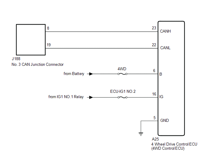
CHECK FOR OPEN IN CAN BUS WIRE (4 WHEEL DRIVE CONTROL ECU [4WD CONTROL ECU] BRANCH WIRE)
(a) Disconnect the cable from the negative (-) battery terminal.
(b) Disconnect the 4 wheel drive control ECU (4WD control ECU) connector.
Rear view of wire harness connector
(to 4 wheel drive control ECU [4WD control ECU])
(c) Measure the resistance according to the value(s) in the table below.
Cable disconnected from negative (-) battery terminal
REPAIR OR REPLACE CAN BRANCH WIRE OR CONNECTOR
CHECK HARNESS AND CONNECTOR (POWER SOURCE CIRCUIT)
(a) Measure the resistance according to the value(s) in the table below.
Cable disconnected from negative (-) battery terminal
Rear view of wire harness connector
(to 4 wheel drive control ECU [4WD control ECU])
(b) Reconnect the cable to the negative (-) battery terminal.
When disconnecting the cable, some systems need to be initialized after the cable is reconnected.
(c) Measure the voltage according to the value(s) in the table below.