Toyota Tundra, 2013 — 2020 (XK150)
Здравствуйте, производил установку S96v2 на Toyota Tundra 2019 г.в., ключ, АКПП, бензин. Авто чистокровный американец. Кан шину подключал на щитке приборов, белый разъем. Цвета голубой и белый(витая пара). Располагались в углу разъема. Сигнал педали тормоза по кану не отображался, подключил по аналогу. Обязательно делать имитацию ключа в замке. Иначе при А/З и Д/З срабатывает штатная сигнализация на 5 секунд(свет+сигнал).
Хочу спросить почему нельзя в гибкой логике добавить понимание команды со штатного брелка при нажатии один раз на кнопку(любую, закрыть или открыть и тд.)? Ведь есть понимание тройного нажатия одной из кнопок или одновременное нажатие двух кнопок. Это я веду к тому, что при включенном зажигании или заведенном двигателе штатная сигнализация(ЦЗ) не реагирует на нажатие кнопок на штатном ключе(закрыть, открыть). На некоторых авто это можно реализовать программно(VAG например). Эта функция была бы удобна для полноценно «Slaveва», открытие и закрытие ЦЗ во всех режимах штатным ключем. То есть при А/З подойдя к авто нажимаем кнопку открытие на штатном ключе(штатная не открывает), сигнализация видит эту команду и через гибкую логику сама открывает автомобиль.
В меню S96v2 я видел пункт доп. управление ЦЗ при включенном зажигании, он мне не помог.
Возможно я что-то упустил и этот функционал уже реализован, подскажите пожалуйста.
Отдельное спасибо Ивану из техподдержки.
С уважением Александр Глазунов
Toyota Tundra Service Manual: System Description
(a) The Controller Area Network (CAN) is a serial data communication system for real time application. It is a vehicle multiplex communication system which has a high communication speed and the ability to detect malfunctions.
(b) Using the CANH and CANL bus lines as a pair, CAN communication is performed using a voltage differential. (A base voltage is applied to the pair of lines and a voltage differential is created when communicating.)
(c) Many ECUs or sensors installed to the vehicle operate by sharing information and communicating with each other.
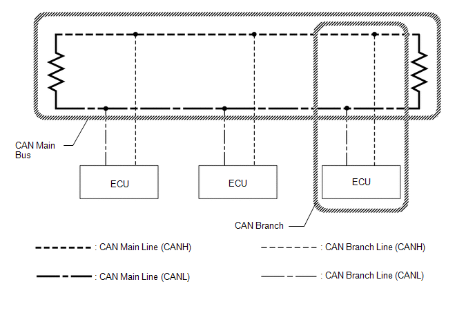
(d) 2 resistors which are necessary for communication are used in a CAN bus main line.
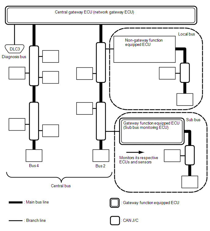
(1) The central bus is a generic name for multiple subordinate CAN bus lines on the central gateway ECU (network gateway ECU).
A bus is displayed as Bus on the «Communication Bus Check» screen of the Techstream.
(1) A sub bus is a bus that has a gateway function equipped ECU in order to communicate with the central bus and other sub buses.
- A sub bus is displayed as Sub bus on the «Communication Bus Check» screen of the Techstream.
- When Sub bus is selected on the «Communication Bus Check» screen, ECUs and sensors connected to non-CAN networks such as LIN may also be displayed in addition to the ECUs and sensors connected to sub buses in the CAN network.
(1) A local bus is a bus that does not have the ability to communicate with other buses. ECUs and sensors on a local bus can only communicate with other ECUs and sensors on the same bus.
Gateway function not equipped ECU is a generic name for ECUs not connected to the central gateway ECU (network gateway ECU) with a gateway function.
(1) A CAN junction connector is a connector that connects branch lines to a main bus.
(1) A main bus line is the wire harness that runs between the 2 terminating resistors of a bus.
(1) A branch line is a wire harness that connects an ECU or sensor to a main bus line.
(1) Terminating resistors which maintain a stable signal inside the CAN bus are installed. 2 resistors of 120 Ω each located at each end of the bus are necessary.
- except Diagnosis Bus: 2 resistors of 120 Ω each located at each end of the bus are necessary.
- for Diagnosis Bus: 1 resistor of 60 Ω located at end of the bus are necessary.

