NISSAN PATROL 1998 Y61 / 5.G Electrical System Workshop Manual
NISSAN PATROL 1998 Y61 / 5.G Electrical System Workshop Manual PATROL 1998 Y61 / 5.G NISSAN NISSAN https://www.carmanualsonline.info/img/5/616/w960_616-0.png NISSAN PATROL 1998 Y61 / 5.G Electrical System Workshop Manual
Page 1 of 326
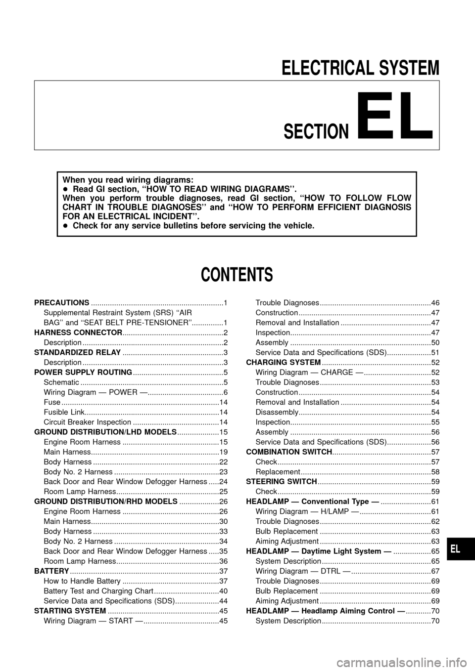
ELECTRICAL SYSTEM
SECTION
EL
When you read wiring diagrams:
+Read GI section, «HOW TO READ WIRING DIAGRAMS».
When you perform trouble diagnoses, read GI section, «HOW TO FOLLOW FLOW
CHART IN TROUBLE DIAGNOSES» and «HOW TO PERFORM EFFICIENT DIAGNOSIS
FOR AN ELECTRICAL INCIDENT».
+Check for any service bulletins before servicing the vehicle.
CONTENTS
PRECAUTIONS. 1
Supplemental Restraint System (SRS) «AIR
BAG» and «SEAT BELT PRE-TENSIONER». 1
HARNESS CONNECTOR. 2
Description . 2
STANDARDIZED RELAY. 3
Description . 3
POWER SUPPLY ROUTING. 5
Schematic . 5
Wiring Diagram Ð POWER Ð. 6
Fuse . 14
Fusible Link. 14
Circuit Breaker Inspection . 14
GROUND DISTRIBUTION/LHD MODELS. 15
Engine Room Harness . 15
Main Harness. 19
Body Harness . 22
Body No. 2 Harness . 23
Back Door and Rear Window Defogger Harness . 24
Room Lamp Harness. 25
GROUND DISTRIBUTION/RHD MODELS. 26
Engine Room Harness . 26
Main Harness. 30
Body Harness . 33
Body No. 2 Harness . 34
Back Door and Rear Window Defogger Harness . 35
Room Lamp Harness. 36
BATTERY. 37
How to Handle Battery . 37
Battery Test and Charging Chart . 40
Service Data and Speci®cations (SDS). 44
STARTING SYSTEM. 45
Wiring Diagram Ð START Ð . 45Trouble Diagnoses. 46
Construction . 47
Removal and Installation . 47
Inspection. 47
Assembly . 50
Service Data and Speci®cations (SDS). 51
CHARGING SYSTEM. 52
Wiring Diagram Ð CHARGE Ð . 52
Trouble Diagnoses. 53
Construction . 54
Removal and Installation . 54
Disassembly. 54
Inspection. 55
Assembly . 56
Service Data and Speci®cations (SDS). 56
COMBINATION SWITCH. 57
Check . 57
Replacement . 58
STEERING SWITCH. 59
Check . 59
HEADLAMP Ð Conventional Type Ð. 61
Wiring Diagram Ð H/LAMP Ð . 61
Trouble Diagnoses. 62
Bulb Replacement . 63
Aiming Adjustment . 63
HEADLAMP Ð Daytime Light System Ð. 65
System Description . 65
Wiring Diagram Ð DTRL Ð . 67
Trouble Diagnoses. 69
Bulb Replacement . 69
Aiming Adjustment . 69
HEADLAMP Ð Headlamp Aiming Control Ð. 70
System Description . 70
EL
Page 2 of 326
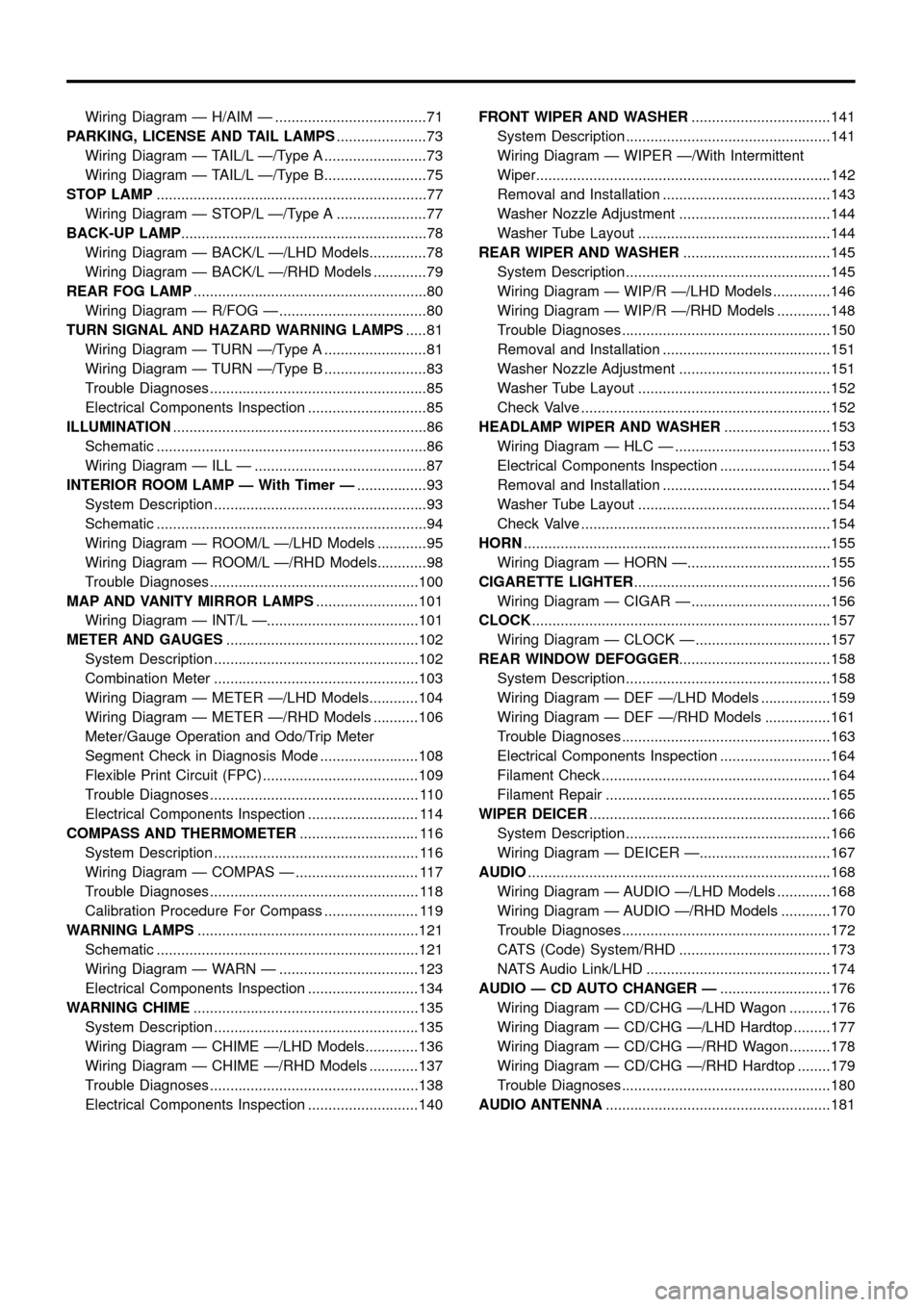
Wiring Diagram Ð H/AIM Ð . 71
PARKING, LICENSE AND TAIL LAMPS. 73
Wiring Diagram Ð TAIL/L Ð/Type A . 73
Wiring Diagram Ð TAIL/L Ð/Type B. 75
STOP LAMP. 77
Wiring Diagram Ð STOP/L Ð/Type A . 77
BACK-UP LAMP. 78
Wiring Diagram Ð BACK/L Ð/LHD Models. 78
Wiring Diagram Ð BACK/L Ð/RHD Models . 79
REAR FOG LAMP. 80
Wiring Diagram Ð R/FOG Ð . 80
TURN SIGNAL AND HAZARD WARNING LAMPS. 81
Wiring Diagram Ð TURN Ð/Type A . 81
Wiring Diagram Ð TURN Ð/Type B . 83
Trouble Diagnoses. 85
Electrical Components Inspection . 85
ILLUMINATION. 86
Schematic . 86
Wiring Diagram Ð ILL Ð . 87
INTERIOR ROOM LAMP Ð With Timer Ð. 93
System Description . 93
Schematic . 94
Wiring Diagram Ð ROOM/L Ð/LHD Models . 95
Wiring Diagram Ð ROOM/L Ð/RHD Models. 98
Trouble Diagnoses. 100
MAP AND VANITY MIRROR LAMPS. 101
Wiring Diagram Ð INT/L Ð. 101
METER AND GAUGES. 102
System Description . 102
Combination Meter . 103
Wiring Diagram Ð METER Ð/LHD Models. 104
Wiring Diagram Ð METER Ð/RHD Models . 106
Meter/Gauge Operation and Odo/Trip Meter
Segment Check in Diagnosis Mode . 108
Flexible Print Circuit (FPC) . 109
Trouble Diagnoses. 110
Electrical Components Inspection . 114
COMPASS AND THERMOMETER. 116
System Description . 116
Wiring Diagram Ð COMPAS Ð . 117
Trouble Diagnoses. 118
Calibration Procedure For Compass . 119
WARNING LAMPS. 121
Schematic . 121
Wiring Diagram Ð WARN Ð . 123
Electrical Components Inspection . 134
WARNING CHIME. 135
System Description . 135
Wiring Diagram Ð CHIME Ð/LHD Models. 136
Wiring Diagram Ð CHIME Ð/RHD Models . 137
Trouble Diagnoses. 138
Electrical Components Inspection . 140FRONT WIPER AND WASHER. 141
System Description . 141
Wiring Diagram Ð WIPER Ð/With Intermittent
Wiper. 142
Removal and Installation . 143
Washer Nozzle Adjustment . 144
Washer Tube Layout . 144
REAR WIPER AND WASHER. 145
System Description . 145
Wiring Diagram Ð WIP/R Ð/LHD Models . 146
Wiring Diagram Ð WIP/R Ð/RHD Models . 148
Trouble Diagnoses. 150
Removal and Installation . 151
Washer Nozzle Adjustment . 151
Washer Tube Layout . 152
Check Valve . 152
HEADLAMP WIPER AND WASHER. 153
Wiring Diagram Ð HLC Ð . 153
Electrical Components Inspection . 154
Removal and Installation . 154
Washer Tube Layout . 154
Check Valve . 154
HORN. 155
Wiring Diagram Ð HORN Ð. 155
CIGARETTE LIGHTER. 156
Wiring Diagram Ð CIGAR Ð . 156
CLOCK. 157
Wiring Diagram Ð CLOCK Ð . 157
REAR WINDOW DEFOGGER. 158
System Description . 158
Wiring Diagram Ð DEF Ð/LHD Models . 159
Wiring Diagram Ð DEF Ð/RHD Models . 161
Trouble Diagnoses. 163
Electrical Components Inspection . 164
Filament Check . 164
Filament Repair . 165
WIPER DEICER. 166
System Description . 166
Wiring Diagram Ð DEICER Ð. 167
AUDIO. 168
Wiring Diagram Ð AUDIO Ð/LHD Models . 168
Wiring Diagram Ð AUDIO Ð/RHD Models . 170
Trouble Diagnoses. 172
CATS (Code) System/RHD . 173
NATS Audio Link/LHD . 174
AUDIO Ð CD AUTO CHANGER Ð. 176
Wiring Diagram Ð CD/CHG Ð/LHD Wagon . 176
Wiring Diagram Ð CD/CHG Ð/LHD Hardtop . 177
Wiring Diagram Ð CD/CHG Ð/RHD Wagon . 178
Wiring Diagram Ð CD/CHG Ð/RHD Hardtop . 179
Trouble Diagnoses. 180
AUDIO ANTENNA. 181
Page 3 of 326
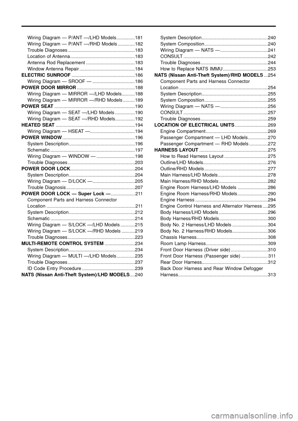
Wiring Diagram Ð P/ANT Ð/LHD Models. 181
Wiring Diagram Ð P/ANT Ð/RHD Models . 182
Trouble Diagnoses. 183
Location of Antenna . 183
Antenna Rod Replacement . 183
Window Antenna Repair . 184
ELECTRIC SUNROOF. 186
Wiring Diagram Ð SROOF Ð . 186
POWER DOOR MIRROR. 188
Wiring Diagram Ð MIRROR Ð/LHD Models. 188
Wiring Diagram Ð MIRROR Ð/RHD Models . 189
POWER SEAT. 190
Wiring Diagram Ð SEAT Ð/LHD Models . 190
Wiring Diagram Ð SEAT Ð/RHD Models. 192
HEATED SEAT. 194
Wiring Diagram Ð HSEAT Ð. 194
POWER WINDOW. 196
System Description . 196
Schematic . 197
Wiring Diagram Ð WINDOW Ð . 198
Trouble Diagnoses. 203
POWER DOOR LOCK. 204
System Description . 204
Wiring Diagram Ð D/LOCK Ð . 205
Trouble Diagnosis . 207
POWER DOOR LOCK Ð Super Lock Ð. 211
Component Parts and Harness Connector
Location . 211
System Description . 212
Schematic . 214
Wiring Diagram Ð S/LOCK Ð/LHD Models . 215
Wiring Diagram Ð S/LOCK Ð/RHD Models . 219
Trouble Diagnoses. 223
MULTI-REMOTE CONTROL SYSTEM. 234
System Description . 234
Wiring Diagram Ð MULTI Ð/LHD Models. 235
Trouble Diagnoses. 237
ID Code Entry Procedure . 239
NATS (Nissan Anti-Theft System)/LHD MODELS. 240System Description . 240
System Composition . 240
Wiring Diagram Ð NATS Ð . 241
CONSULT . 242
Trouble Diagnoses. 244
How to Replace NATS IMMU . 253
NATS (Nissan Anti-Theft System)/RHD MODELS. 254
Component Parts and Harness Connector
Location . 254
System Description . 255
System Composition . 255
Wiring Diagram Ð NATS Ð . 256
CONSULT . 257
Trouble Diagnoses. 259
LOCATION OF ELECTRICAL UNITS. 269
Engine Compartment . 269
Passenger Compartment Ð LHD Models . 270
Passenger Compartment Ð RHD Models . 272
HARNESS LAYOUT. 275
How to Read Harness Layout . 275
Outline/LHD Models. 276
Outline/RHD Models . 277
Main Harness/LHD Models. 278
Main Harness/RHD Models . 282
Engine Room Harness/LHD Models . 286
Engine Room Harness/RHD Models . 290
Engine Harness . 294
Engine Control Harness and Alternator Harness . 295
Body Harness/LHD Models . 296
Body Harness/RHD Models. 300
Body No. 2 Harness/LHD Models . 304
Body No. 2 Harness/RHD Models. 306
Chassis Harness. 308
Room Lamp Harness. 309
Front Door Harness (Driver side) . 310
Front Door Harness (Passenger side) . 311
Rear Door Harness. 312
Back Door Harness and Rear Window Defogger
Harness. 313
Page 4 of 326
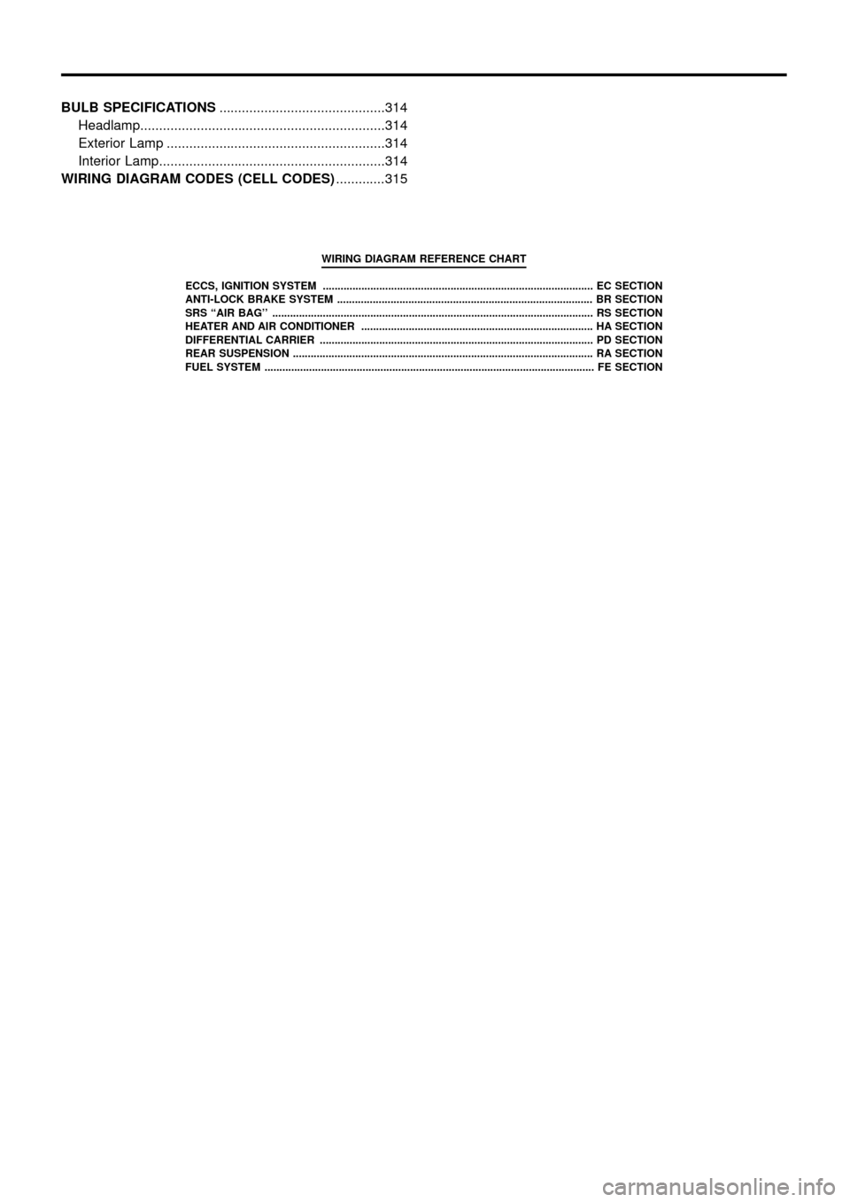
BULB SPECIFICATIONS. 314
Headlamp. 314
Exterior Lamp . 314
Interior Lamp. 314
WIRING DIAGRAM CODES (CELL CODES) . 315
WIRING DIAGRAM REFERENCE CHART
ECCS, IGNITION SYSTEM . \
. EC SECTION
ANTI-LOCK BRAKE SYSTEM . \
. BR SECTION
SRS «AIR BAG» . \
. RS SECT ION
HEATER AND AIR CONDITIONER . \
. HA SECTION
DIFFERENTIAL CARRIER . \
. PD SECTION
REAR SUSPENSION . \
. RA SECTION
FUEL SYSTEM . \
. FE SECT ION
Page 5 of 326
Supplemental Restraint System (SRS) «AIR
BAG» and «SEAT BELT PRE-TENSIONER»
The Supplemental Restraint System such as «AIR BAG» and «SEAT BELT PRE-TENSIONER» used along with
a seat belt, helps to reduce the risk or severity of injury to the driver and front passenger in a frontal collision.
The SRS system composition which is available to NISSAN MODEL Y61 is as follows (The composition var-
ies according to the destination.):
Driver air bag module (located in the center of the steering wheel), front passenger air bag module (located
on the instrument panel on passenger side), seat belt pre-tensioner, a diagnosis sensor unit, warning lamp,
wiring harness and spiral cable.
Information necessary to service the system safely is included in theRS sectionof this Service Manual.
WARNING:
+To avoid rendering the SRS inoperative, which could increase the risk of personal injury or death
in the event of a collision which would result in air bag in¯ation, all maintenance must be performed
by an authorized NISSAN dealer.
+Improper maintenance, including incorrect removal and installation of the SRS, can lead to per-
sonal injury caused by unintentional activation of the system. For removal of Spiral Cable and Air
Bag Module, see the RS section.
+Do not use electrical test equipment on any circuit related to the SRS unless instructed to in this
Service Manual. Spiral cable and wiring harnesses covered with yellow insulation either just before
the harness connectors or for the complete harness are related to the SRS.
PRECAUTIONS
EL-1
Page 6 of 326
Description
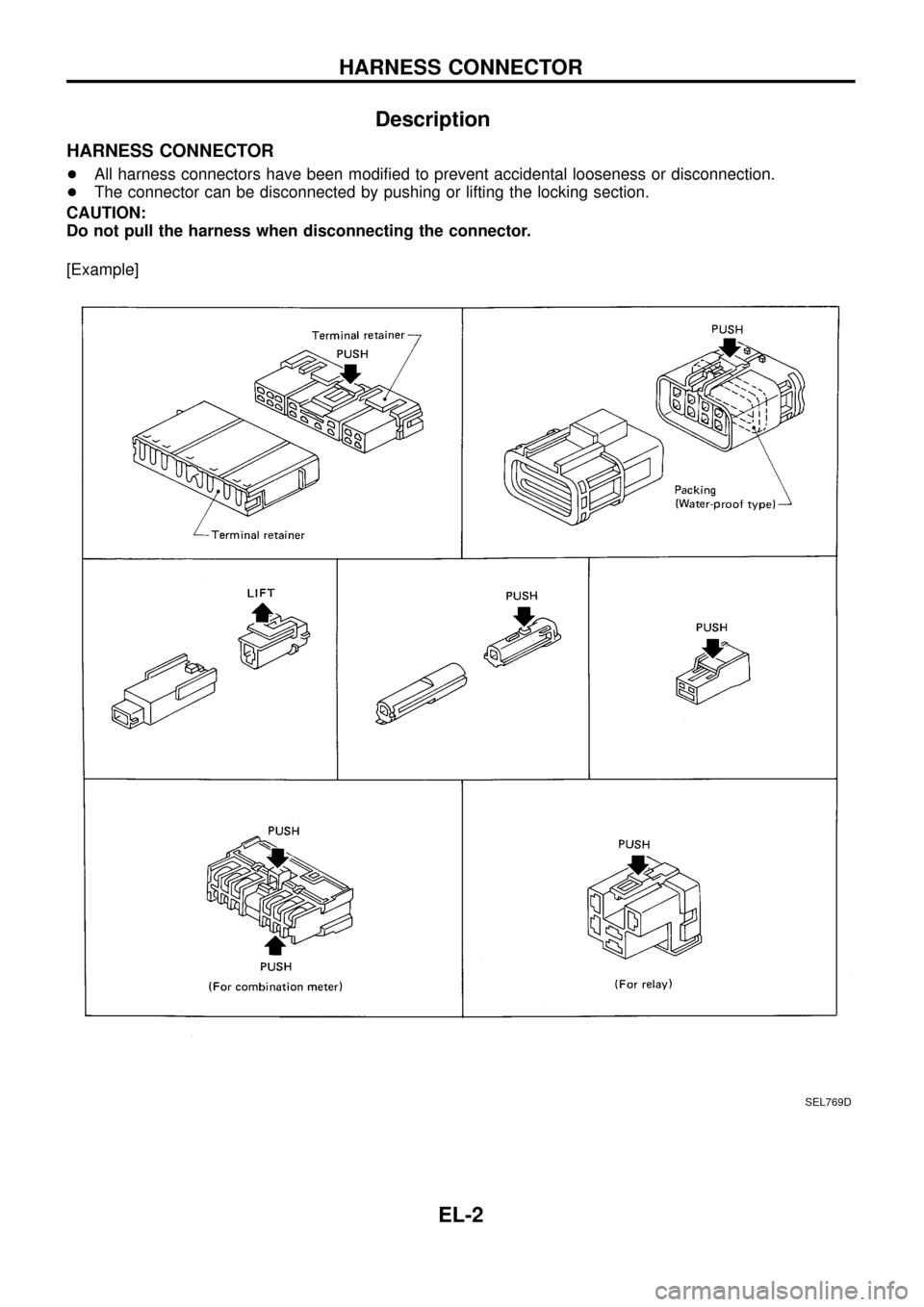
HARNESS CONNECTOR
+All harness connectors have been modi®ed to prevent accidental looseness or disconnection.
+The connector can be disconnected by pushing or lifting the locking section.
CAUTION:
Do not pull the harness when disconnecting the connector.
[Example]
SEL769D
HARNESS CONNECTOR
EL-2
Page 7 of 326
Description
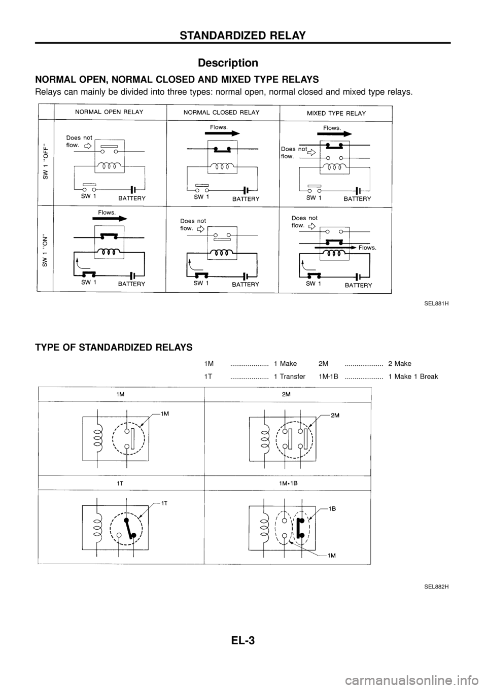
NORMAL OPEN, NORMAL CLOSED AND MIXED TYPE RELAYS
Relays can mainly be divided into three types: normal open, normal closed and mixed type relays.
TYPE OF STANDARDIZED RELAYS
1M . 1 Make 2M . 2 Make
1T . 1 Transfer 1Mz1B . 1 Make 1 Break
SEL881H
SEL882H
STANDARDIZED RELAY
EL-3
Page 8 of 326
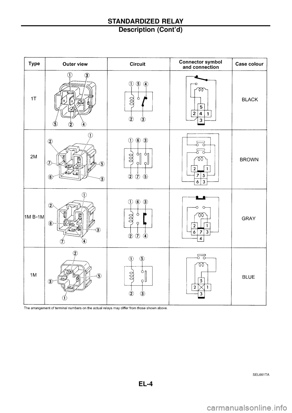
SEL661TA
STANDARDIZED RELAY
Description (Cont’d)
EL-4
Page 9 of 326
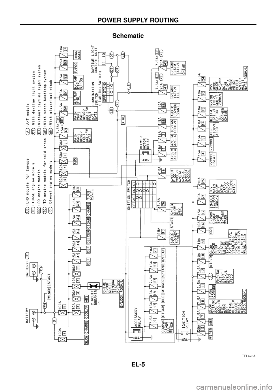
Schematic
TEL478A
POWER SUPPLY ROUTING
EL-5
Page 10 of 326
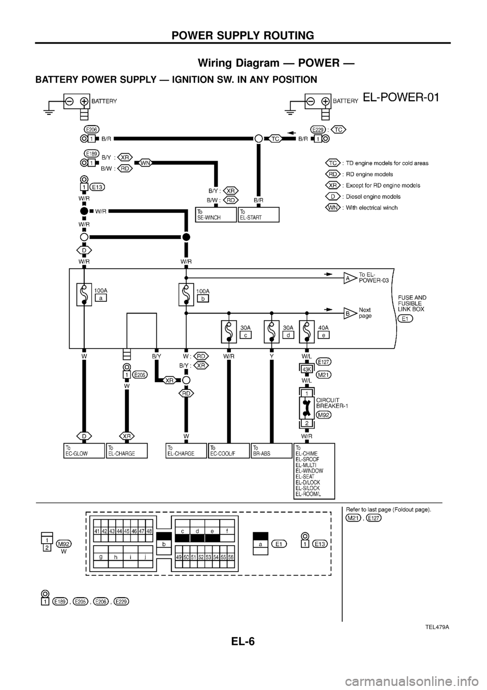
Wiring Diagram Ð POWER Ð
BATTERY POWER SUPPLY Ð IGNITION SW. IN ANY POSITION
TEL479A
POWER SUPPLY ROUTING
EL-6
