- Nissan Murano z50 z51 fuse and relay
- Murano Z50
- Passenger compartment
- Engine compartment
- Fuse and relay box
- Battery fuse box
- High power fuses
- Murano Z51
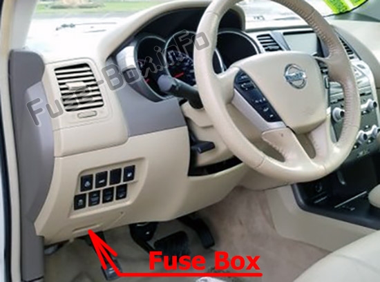
- Passenger compartment
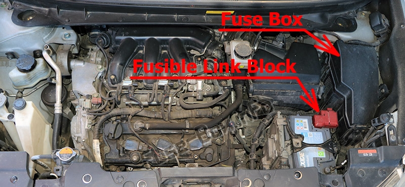
- Engine compartment
- Related posts:
- Nissan Murano (Z51; 2009-2014) fuses and relays
- Fuse Layout Nissan Murano 2009-2014
- Fuse box location
- Fuse box diagram
- Fuse box location
- Fuse box diagram
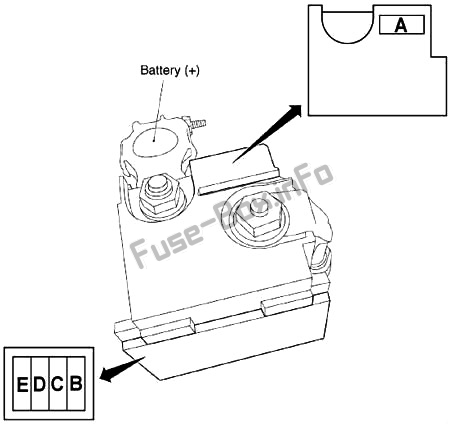
- Fusible Link Block (Main Fuses)
Nissan Murano z50 z51 fuse and relay
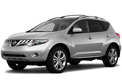
Nissan Murano is a full-fledged crossover. The 3rd generation is currently in production. The first is designated – z50 and was produced in 2002, 2003, 2004, 2005, 2006 and 2007. The second is in 2008, 2009, 2010, 2011, 2012, 2013, 2014, 2015, 2016 and is labeled z51. During this period, the car undergoes restyling several times. In our material you will find a designation of fuses and relays Nissan Murano Z50 and Z51. For clarity, we will also show photographs and box diagrams with the appointment of elements.
The car was delivered to many regions of the world with various trim levels. Check the assignment of the elements with the diagrams on the back of the protective cover in order to obtain an up-to-date description of the fuses.
Murano Z50
Passenger compartment
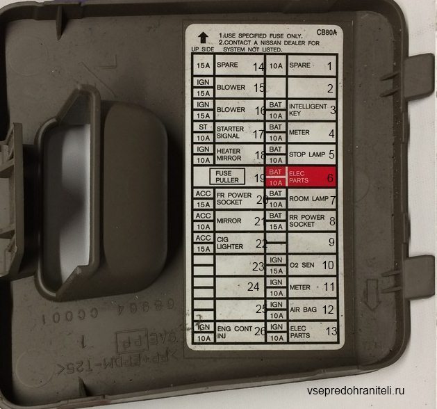
Located in the instrument panel on the left side.
Appointment
- 10A – Spare
- –
- 10A – Smart key
- 10A – Instrument panel
- 15A – Brake lights
- 10A – Electrical equipment
- 10A – Interior light
- 15A – Rear socket
- –
- 15A – Lamba probe (oxygen sensor)
- 10A – Instrument panel
- 10A – Airbags
- 10A – Electronic campaigns
- 15A – Spare
- 10A – Fan
- 10A – Fan
- 10A – Starter
- 10A – Heated mirrors
- –
- 15A – Front socket
- 10A – Power mirrors
- 15A – Cigarette lighter
- –
- –
- –
- 10A – Engine management system
The fuse number 22, 15A, is responsible for the cigarette lighter.
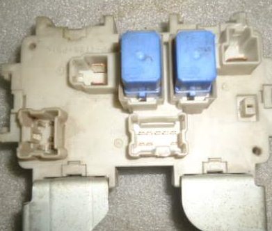
The heater fan relay and the auxiliary ignition circuit relay can be located on the side.
Engine compartment
The boxes can be located in 3 places under the hood.
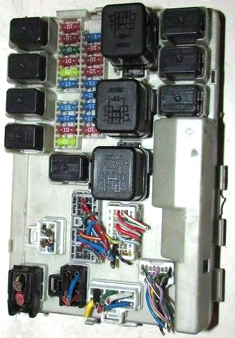
Fuse and relay box
Located on the right side rail.
| 1 | Engine control relay |
| 2 | Headlamp high beam relay |
| 3 | Headlamp low beam relay |
| 4 | Starter relay |
| 5 | Relay for main ignition circuits |
| 6 | |
| 7 | |
| 8 | |
| 9 | Throttle control unit relay |
| 10 | Fuel pump relay |
| 11 | Fog lamp relay |
| F1 | (10A) |
| F2 | (10A) RH headlamp |
| F3 | (30A) Windshield wiper / washer |
| F4 | (10A) LH headlamp |
| F5 | (20A) Heated rear window |
| F6 | (15A) RH headlight |
| F7 | (15 A) |
| F8 | (15A) |
| F9 | (10A) Air conditioner |
| F10 | (20A) Heated rear window |
| F11 | (15A) Fuel pump |
| F12 | (10A) |
| F13 | (10A) Transmission control |
| F14 | (10A) |
| F15 | – |
| F16 | (15A) LH headlamp |
| F17 | (15A) Engine management system |
| F18 | (15A) Fog lights |
| F19 | – |
Battery fuse box
Designation
| 1 | Headlight washer relay |
| 2 | Horn relay |
| F1 | – |
| F2 | (10A) Horn |
| F3 | (10A) Generator |
| F4 | (30A) Trailer socket |
| F5 | (50A) |
| F6 | – |
| F7 | (30A) ABS / ESP system |
| F8 | (40A) Headlamp washers |
| F9 | (50A) ABS / ESP system |
| F10 | (40A) Cooling fan motor |
| F11 | (40A) Cooling fan motor |
| F12 | (40A) Ignition switch circuits |
| F13 | (10A) Tailgate opener |
| F14 | (15A) Heated seats |
| F15 | (10A) 4WD control system |
| F16 | (15 A) |
High power fuses
The positive side of the battery may contain high power fuses.
Murano Z51
Passenger compartment
Legend on the back of the cover
Check with your description! A 15A fuse is responsible for the cigarette lighter, seventh from the bottom, right row.
Engine compartment
Appointment
And if you have something to supplement the material, we will be glad to receive your comments.
Related posts:
Nissan Murano (Z51; 2009-2014) fuses and relays
In this article, we consider the second-generation Nissan Murano (Z51), produced from 2009 to 2014. Here you will find fuse box diagrams of Nissan Murano 2009, 2010, 2011, 2012, 2013 and 2014, get information about the location of the fuse panels inside the car, and learn about the assignment of each fuse (fuse layout) and relay.
Fuse Layout Nissan Murano 2009-2014
Cigar lighter (power outlet) fuses in the Nissan Murano are the fuses #18 (Cigarette Lighter) and #20 (Front Power Socket) in the Instrument panel fuse box.
Fuse box location
The fuse box is located behind the cover on the driver’s side of the dashboard.
Fuse box diagram
Advertisements
Assignment of the fuses and relays in the Instrument Panel
| № | Amp | Description |
|---|---|---|
| 1 | 15 | Front Heated Seat |
| 2 | 10 | AirBag Diagnosis Sensor Unit |
| 3 | 10 | Automatic Back Door Control Unit, ASCD Brake Switch, Stop Lamp Switch, Headlamp Aiming Motor, Electronic Controlled Engine Mount Control Solenoid Valve, Data Link Connector, Steering Angle Sensor, Air Conditioner Amplifier, Heated Seat Relay, Power Steering Control Unit, BCM (Body Control Module), Navi Control Unit, Option Connector, Video Distributor, Auto Anti-Dazzling Inside Mirror, Auto Levelizer Control Unit |
| 4 | 10 | Combination Meter, Back-Up Lamp Relay |
| 5 | 10 | Fuel Lid Opener Relay |
| 6 | 10 | Intelligent Key Warning Buzzer, Data Link Connector, Air Conditioner Amplifier, Automatic Back Door Control Unit, Automatic Back Door Warning Buzzer, Vehicle Tilt Sensor, Siren Control Unit, Rear Seatback Power Return Control Unit, Light & Rain Sensor |
| 7 | 10 | Stop Lamp Switch, BCM (Body Control Module) |
| 8 | — | Not Used |
| 9 | 10 | Key Slot, Security Indicator Lamp, Push-Button Ignition Switch |
| 10 | 10 | Seat Memory Switch, BCM (Body Control Module) |
| 11 | 10 | Combination Meter, Transmission Control Module (TCM) |
| 12 | — | Not Used |
| 13 | 10 | Door Mirror Defogger, Air Conditioner Amplifier |
| 14 | 20 | Rear Window Defogger |
| 15 | 20 | Rear Window Defogger |
| 16 | — | Not Used |
| 17 | — | Not Used |
| 18 | 15 | Cigarette Lighter Socket |
| 19 | 10 | Audio, Front Display, Air Conditioner Amplifier, Rear Display, Navi Control Unit, DVD Player, Video Distributor, Camera Control Unit, Power Socket Relay, BCM (Body Control Module), Multifunction Switch, Door Mirror Remote Control Switch |
| 20 | 15 | Front Power Socket |
| 21 | 15 | Blower Motor |
| 22 | 15 | Blower Motor |
| Relays | ||
| R1 | Ignition | |
| R2 | Rear Window Defogger | |
| R3 | Accessory | |
| R4 | Front Blower |
Fuse box location
Advertisements
Fuse box diagram
Assignment of the fuses and relays in the Engine Compartment
| № | Amp | Description |
|---|---|---|
| 23 | 15 | BOSE Amplifier |
| 24 | 15 | BOSE Amplifier |
| 25 | 15 | Woofer |
| 31 | 20 | Option Connector |
| 32 | 15 | Rear Seatback Power Return Control Unit |
| 33 | 20 | Power Socket Relay |
| 34 | 20 | Heated Seat Relay |
| 35 | 20 | Audio, Front Display, Rear Display, Navi Control Unit, DVD Player, Video Distributor, Camera Control Unit |
| 36 | 15 | 4WD Control Unit |
| 37 | 10 | Horn Relay |
| 38 | 15 | Generator, Vehicle Security Horn Relay |
| F | 40 | ABS |
| G | 40 | ABS |
| H | — | Not Used |
| I | 50 | Ignition Relay (Fuses 1, 2, 3, 4), IPDM E/R |
| J | 40 | Circuit Breaker (Automatic Back Door Control Module) |
| K | 40 | Cooling Fan Relay 2, Cooling Fan Relay 3 |
| L | 40 | BCM (Body Control Module), Circuit Breaker (Automatic Drive Positioner Control Unit, Driver Seat Control, Lumbar Support Switch) |
| M | 40 | Cooling Fan Motor 1 |
| 41 | 15 | Fuel Pump Relay |
| 42 | 10 | Cooling Fan Relay 2, Cooling Fan Relay 3 |
| 43 | 10 | Secondary Speed Sensor, Transmission Control Module (TCM) |
| 44 | 10 | Injectors, Engine Control Module (ECM) |
| 45 | 10 | ABS, 4WD Control Unit |
| 46 | 15 | Air Fuel Ratio Sensor, Heated Oxygen Sensor |
| 47 | 10 | Combination Switch |
| 48 | 10 | Steering Lock Relay |
| 49 | 10 | Air Conditioner Relay |
| 50 | 15 | Engine Control Module Relay (VIAS Control Solenoid, Intake Valve Timing Control Solenoid Valve, Condenser, Ignition Coils, Engine Control Module, Mass Air Flow Sensor, EVAP Canister Purge Volume Control Solenoid Valve) |
| 51 | 15 | Throttle Control Motor Relay |
| 52 | 10 | Parking Lamp |
| 53 | 10 | Rear Combination Lamp, License Plate Lamp, Mood Lamp Center, Map Lamp, Front Heated Seat Switch, Rear Heated Seat Switch, Option Connector, ESP Off Switch, 4WD Lock Switch, Ashtray Illumination, Cluster Illumination, Glove Box Lamp, Combination Switch (Spiral Cable), Hazard Switch, Control Device Illumination, Automatic Back Door Main Switch, Automatic 8ack Door Switch, Front Power Return Switch, Multifunction Switch, Navi Control Unit, DVD Player, Door Mirror Remote Control Switch, Front Door Insioe Handle Illumination, Auto Levelizer Control Unit |
| 54 | 10 | Headlamp High (left) |
| 55 | 10 | Headlamp High (right) |
| 56 | 15 | Headlamp Low (left) |
| 57 | 15 | Headlamp Low (right) |
| 58 | 15 | Front Fog Lamp Relay |
| 59 | 10 | Daytime Running Light Relay |
| 60 | 30 | Front Wiper Relay |
| 61 | 40 | Headlamp Washer Relay |
| R1 | — | Horn Relay |
Advertisements
Fusible Link Block (Main Fuses)
It is located on the positive terminal of the battery
Fusible Link Block
| № | Amp | Description |
|---|---|---|
| A | 250 | Generator, Starter, Fuses B, C |
| B | 100 | Fuses F, G, I, J, K, L, M, 31, 32, 33, 34, 35, 36, 37, 38 |
| C | 60 | Headlamp High Relay (Fuses 54, 55), Headlamp Low Relay (Fuses 56, 57), Tail Lamp Relay (Fuses 52, 53), Fuses 58, 59, 60 |
| D | 100 | Accessory Relay (Fuses 18, 19, 20), Rear Window Defogger Relay (Fuses 13, 14, 15), Blower Relay (Fuses 21, 22), Fuses 5, 6, 7, 9, 10, 11, 23, 24, 25, 61 |
| E | 80 | Ignition Relay (Fuses 41, 42, 43, 44, 45, 46, 47), Fuses 48, 49, 50, 51 |


