- 2020 Jeep Grand Cherokee Owners Manual — LIFTGATE
- To Unlock/Enter The Liftgate
- NOTE:
- Passive Entry/Lock Button Location
- NOTE:
- Closing
- To Lock The Liftgate
- NOTE:
- Power Liftgate — If Equipped
- NOTE:
- NOTE:
- Cargo Area Features
- NOTE:
- Rear Storage Bin
- Tether Strap
- Rear Lower Storage Bins Retractable Cargo Area Cover — If Equipped
- NOTE:
- Rear Cargo Cover
- Jeep WJ Grand Cherokee Liftgate Trim and Components
- Trim panel removal
- Reinstalling the trim panel
- Liftgate interior components
- Liftgate cable and latch adjustments
- Liftgate manual unlock / lock lever
- Flip-up glass prop rods
- Liftgate glass support rods
2020 Jeep Grand Cherokee Owners Manual — LIFTGATE
The liftgate can be opened from inside the vehicle using the power liftgate button on the overhead console, using the key fob outside of the vehicle or the electronic liftgate release.
To Unlock/Enter The Liftgate
The liftgate may be released in several ways:
The liftgate passive entry unlock feature is built into the elec- tronic liftgate release. With a valid Passive Entry key fob within 5 ft (1.5 m) of the liftgate, push the electronic liftgate release to open with one fluid motion. Push the button on the key fob twice within five seconds to release the liftgate.
NOTE:
If “Unlock All Doors 1st Press” is programmed in the instru- ment cluster display, all doors will unlock when you push the electronic release on the liftgate. If «Unlock Driver Door 1st Press» is programmed in Uconnect, only the liftgate will unlock when you push the electronic release on the liftgate. Refer to “Uconnect Settings” in “Multimedia” for further information.

Passive Entry/Lock Button Location
NOTE:
Use the power door lock switch on either front door trim panel or the key fob to lock and unlock the liftgate. The manual door locks on the doors and the driver’s door lock cylinder will not lock and unlock the liftgate.
Closing
To manually close the liftgate, grasp the liftgate closing handle and initiate the lowering of the liftgate. Release the handle when the liftgate is partially closed and the momentum will fully close the liftgate.
To Lock The Liftgate
With a valid Passive Entry key fob within 5 ft (1.5 m) of the liftgate, pushing the Keyless Enter-N-Go — Passive Entry lock button located next to the outside handle release will lock the vehicle.
The power liftgate may be closed by pushing the button, located in the upper left trim in the liftgate opening. Pushing button will only close the liftgate. This button cannot be used to open the liftgate.
NOTE:
The liftgate unlock feature is built into the electronic liftgate release.
Power Liftgate — If Equipped

The power liftgate may be opened by pushing the electronic liftgate release (refer to “Keyless Enter-N-Go — Passive Entry” located in “Getting To Know Your Vehicle” for further information), or by pushing the liftgate button on the key fob. Push the liftgate button on the key fob twice within five seconds to open the power lift- gate. Once the liftgate is open, pushing the button twice within five seconds a second time will close the liftgate.
The power liftgate may also be opened or closed by pushing the liftgate button located on the front overhead console. If the liftgate is fully open, the liftgate can be closed by pushing the liftgate button located on the left rear trim panel, near the liftgate opening. If the liftgate is in motion, pushing the lift- gate button located on the left rear trim panel will reverse the liftgate.
When the liftgate button on the key fob is pushed two times, the turn signals will flash to signal that the liftgate is opening or closing (if Flash Lamps with Lock is enabled in the Ucon- nect settings), and the liftgate chime will be audible. Refer to «Uconnect Settings» in «Multimedia” for further information.
NOTE:
- In the event of a power malfunction to the liftgate, an emergency liftgate latch release can be used to open the liftgate. The emergency liftgate latch release can be accessed through a snap-in cover located on the liftgate trim panel.
- If liftgate is left open for an extended period of time, the liftgate may need to be closed manually to reset power lift- gate functionality.
NOTE:
- The power liftgate will not operate in temperatures below −22°F (−30°C) or temperatures above 150°F (65°C). Be sure to remove any buildup of snow or ice from the liftgate before pushing any of the power liftgate switches.
- If anything obstructs the power liftgate while it is closing or opening, the liftgate will automatically reverse to the closed or open position, provided it meets sufficient resistance.
- There are also pinch sensors attached to the side of the lift- gate. Light pressure anywhere along these strips will cause the liftgate to return to the open position.
- If the liftgate is not fully open, push the liftgate button on the key fob twice to operate the liftgate.
- If the electronic liftgate release is pushed while the power liftgate is closing, the liftgate will reverse to the full open position.
- If the electronic liftgate release is pushed while the power liftgate is opening, the liftgate motor will disengage to allow manual operation.
- If the power liftgate encounters multiple obstructions within the same cycle, the system will automatically stop and the liftgate must be opened or closed manually.
Cargo Area Features
There are up to four removable storage bins located in the rear cargo area. There are two storage bins located on either side of the cargo area.
NOTE:
If your vehicle is equipped with a rear subwoofer, the storage bin on that side will not be available.

Rear Storage Bin
Two additional storage bins are located under the load floor. To access the lower storage bins, raise the load floor and attach the tether strap (attached to the bottom of the load floor) to the liftgate opening.

2
Tether Strap

Rear Lower Storage Bins Retractable Cargo Area Cover — If Equipped
NOTE:
The purpose of this cover is for privacy, not to secure loads. It will not prevent cargo from shifting or protect passengers from loose cargo.
- Grasp the cover at the center handle. Pull it over the cargo area.
- Insert the pins on the ends of the cover into the slots in the pillar trim cover.
- The liftgate may be opened with the cargo cover in place.

Rear Cargo Cover
The rear cargo tie-downs, located on the cargo area floor, should be used to safely secure loads when the vehicle is moving.
Jeep WJ Grand Cherokee Liftgate Trim and Components
Welcome to the JeepSpecs.com in-depth page of WJ Generation Jeep Grand Cherokee trim and components. Did we mis anything? Please get in touch with us and tell us about it!
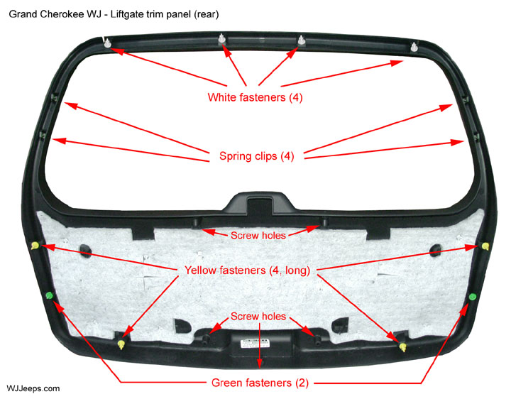
The liftgate trim panel is attached with 5 screws, 4 spring clips and 10 plastic fasteners
Trim panel removal
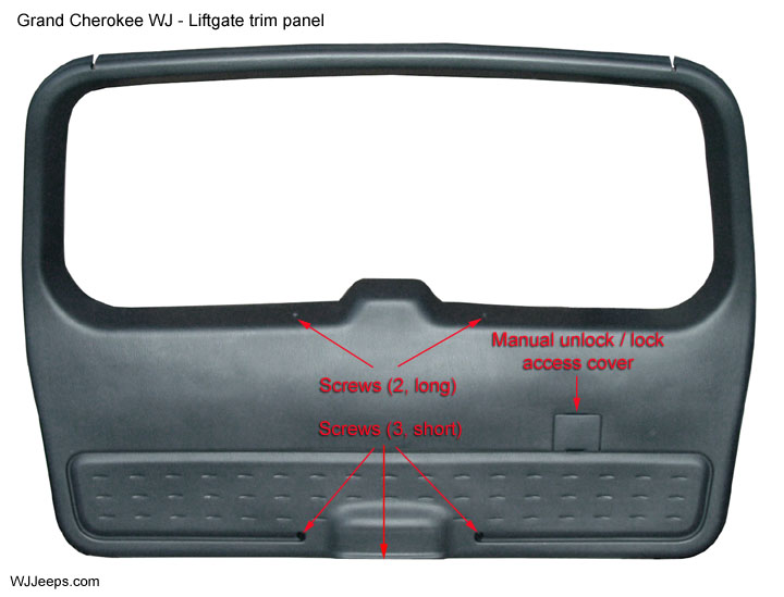
2. Remove the 5 phillips screws securing the liftgate trim panel to the liftgate
3. Disconnect both rear window defroster wires, which are locked into place (See photo below).
4. Using a trim stick or equivalent, carefully pry the liftgate trim panel off the liftgate. There are 10 plastic fasteners used on the liftgate, with 3 different sizes used. These break easily so it is a good idea to have a few spares on hand.
5. To access the interior components, remove the black insulator cover from the liftgate. This is attached with a light adhesive and can slowly be pulled off.

Defrost connectors: Press the tab on the connector to release it and carefully wiggle the connector out. Keep it parallel to the glass, do not bend it up or down.

The black vinyl insulator cover is attached with a mild adhesive
Reinstalling the trim panel
1. Inspect all 10 of the plastic fasteners, making sure they are locked in place and straight, and that they are not broken or damaged.
2. If you have removed the black insulator pad, reinstall it, working from one side to the other, making sure that the cut-out holes are aligned properly. Take a small towel and rub around the edges to nicely seal it back in place.
3. With the liftgate fully open, lift the trim piece and hold in the approximate position up against the liftgate. Start by aligning the two yellow bottom fasteners into their holes, once both are lined up, hit the trim with your palm in the area directly above each fastener to lock them firmly in place. Next, align the next two plastic fasteners on one side, and then the other side, and snap them into place. You should now have all 6 lower connectors fastened.
4. At the top portion of the trim piece, check that the coiled defroster wires are routed through their slots that are cut in to the top of the trim panel.
5. Align each of the 4 top white fasteners, starting them in their holes and lightly holding the trim panel in place to keep them from slipping out. Also make sure the 4 spring clips are lined up as well. When everything is lined up, tap each area above the fastener firmly with your palm to seat them into place.
6. Check the entire perimiter of the trim panel to make sure it is seated flat against the liftgate. Install the 3 short lower phillips screws. Close the liftgate and open the liftgate window. This will allow easier access to line up the two long screws that are by the window latch. You may have to pull the trim towards you a little and move it as sometimes the screws are tough to align in their holes.
7. Carefully reconnect the two defroster wires, making sure they “lock” into place.
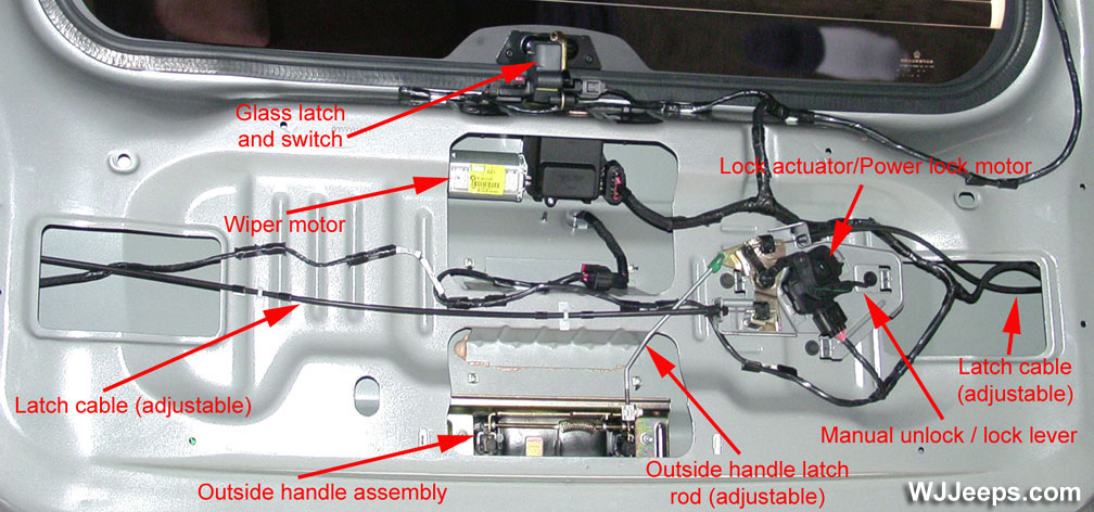
Liftgate interior components
Liftgate cable and latch adjustments
Latch adjustment:
(1) With the liftgate closed, slowly open the liftgate using the outside handle.
(2) Determine if excessive handle travel is required to unlatch the liftgate. If so, adjustment to the latch rod may be required.
(3) Open the plastic latch rod retention clip on the outside handle and disconnect the latch rod from the outside handle.
(4) Verify that the latch control assembly is in its fully returned position.
NOTE: Do not pre-load the latch rod when attaching.
(5) Attach the threaded end of the latch rod to the open retention clip. Make sure all excess play has been removed between the outside liftgate handle and the latch assembly.
(6) Fully close the plastic retention clip.
(7) Cycle the outside handle and verify smooth operation.
(1) Determine if one of more of the following occurs:
– Excessive handle travel is required to unlatch the liftgate.
– Only one side of the liftgate will unlatch.
– As one side of the liftgate unlatches, more than 2 mm (0.08 in.) of additional outside handle travel is required to unlatch the other side (latches are not synchronized/timed).
NOTE: Do not close the liftgate during the adjustment procedure.
(2) To adjust the latch cables, open the liftgate.
(3) Open the plastic latch rod retention clip on the outside handle and disconnect the latch rod from the outside handle.
(4) Open both latch cable retention clips and remove the threaded end of the cable from each clip.
(5) Verify that the latch control assembly is in its fully returned position.
(6) Verify that both latch cables slide smoothly and do not bind.
NOTE: The latches must be in their fully closed position to properly adjust the latch cables. The following step is necessary to remove excess cable play at the latch end of the cable.
(7) Using a suitable tool, fully latch (close) both liftgate latches.
(9) Remove the excess play from the other latch cable and seat both cable threaded ends into their respective opened retention clips.
NOTE: Apply a small bead of RTV to both open cable retention clips and threaded cable ends to prevent the threaded ends from rotating within the retention clips.
(10) Close both cable retention clips. Verify complete clip closure.
(11) Adjust the outside handle rod (see above section).
(12) While the liftgate is open and the latch control assembly is still uncovered, slowly open the outside latch handle to unlatch both side latches. Verify both latches unlatch.
(13) Cycle the liftgate closed and open to verify correct operation of the liftgate latch system.
Liftgate manual unlock / lock lever

All WJs feature an emergency unlock/lock switch lever for the liftgate. Should the liftgate become locked and unable to be opened due to a switch or circuit failure, a manual unlock/lock lever is accessible behind a small panel on the interior trim panel. As shown in the photos above, the lever can be moved up or down to unlock or lock the liftgate door.
Flip-up glass prop rods
1. Open the liftgate glass
2. Using a trim stick or equivalent, gently pry open the locking cap on the top end of the prop rod
3. Rotate prop downwards to disconnect it from the lower ball stud.
4. Install new cylinder in place
5. Compress locking cap to lock the rod on the ball stud. Lower window slowly to verify proper operation
Liftgate glass support rods
1. Open and support the liftgate. It easiest (and probably safer) to also have a second person help out and support each side of the liftgate as each rod is being changed. Rods should be replaced in pairs.
2. Remove the two T-40 torx screws attaching the rod to the liftgate and vehicle body and remove the rod.
3. Install new support rod and tighten the Torx screws
4. Lower liftgate slowly to verify proper operation