G sensor nissan juke
Description
ECM stores calibration data (inherent characteristic value) of G sensor to provide accurate control. Therefore, it is required to perform calibration of G sensor after the following work is performed.
� Removal/installation or replacement of G sensor � Replacement of ECM
Work Procedure
1.PREPARATION BEFORE CALIBRATION PROCEDURE
1. Park the vehicle on a level surface.
2. Adjust air pressure of all tires to the specified pressure. WT-9, «Tire Air Pressure».
1. Turn ignition switch ON.
CAUTION:
Never start engine.
2. Select �Work Support� mode in �ENGINE.
3. Select �G SENSOR CALIBRATION�.
Never swing the vehicle during �G sensor calibration
Is �COMPLETED� displayed? YES >> END NO >> Perform steps 1 and 2 again.
Idle air volume learning
Description Idle Air Volume Learning is a function of ECM to learn the idle air volume that keeps each engine idle speed within the specific range. It must be performed under any of the following .
Mixture ratio self-learning value clear
Description This describes how to erase the mixture ratio self-learning value. For the actual procedure, follow the instructions in �Diagnosis Procedure�. Work Procedure With CONSULT-III 1. Sta .
Other materials:
Front combination lamp
Exploded View REMOVAL 1. Front combination lamp : N�m (kg-m, in-lb) DISASSEMBLY 1. Parking lamp bulb 2. Parking lamp bulb socket 3. Front turn signal lamp bulb socket 4. Front turn signal lamp bulb 5. Front combination lamp housing Removal and Installation CAUTION: Disconnect the .
Hoses
HOSE REMOVAL AND INSTALLATION � To prevent damage to rubber hose, do not pry off rubber hose with tapered tool or screwdriver. � To reinstall the rubber hose securely, check that hose insertion length and orientation is correct. (If tube is equipped with hose stopper, insert rubber hose into .
Diagnosis system (bcm) (with intelligent key system)
Common item COMMON ITEM : CONSULT-III Function (BCM — COMMON ITEM) APPLICATION ITEM CONSULT-III performs the following functions via CAN communication with BCM. SYSTEM APPLICATION BCM can perform the following functions for each system. NOTE: It can perform the diagnosis modes except the .
G sensor nissan juke
For M/T models : DTC Logic
DTC CONFIRMATION PROCEDURE
If DTC Confirmation Procedure has been previously conducted, always perform the following procedure before conducting the next test.
1. Turn ignition switch OFF and wait at least 10 seconds.
2. Turn ignition switch ON.
3. Turn ignition switch OFF and wait at least 10 seconds.
TEST CONDITION:
Before performing the following procedure, confirm that battery voltage is more than 11 V at idle
2.PERFORM DTC CONFIRMATION PROCEDURE
1. Start engine and let it idle for at least 5 seconds.
Is 1st trip DTC detected? YES >> Proceed to EC-356, «FOR M/T MODELS : Diagnosis Procedure».
For M/T models : Diagnosis Procedure
1.CHECK G SENSOR POWER SUPPLY CIRCUIT-I
1. Turn ignition switch OFF.
2. Disconnect G sensor harness connector.
3. Turn ignition switch ON.
4. Check the voltage between G sensor harness connector terminals.
Is the inspection result normal? YES >> GO TO 2.
2.CHECK G SENSOR SIGNAL CIRCUIT
1. Turn ignition switch OFF.
2. Disconnect ECM harness connector.
3. Check the continuity between G sensor harness connector and ECM harness connector.
4. Also check harness for short to ground and short to power.
Is the inspection result normal? YES >> GO TO 3.
NO >> Repair or replace error-detected parts.
Check G sensor. Refer to EC-357, «FOR M/T MODELS : Component Inspection».
Is the inspection result normal? YES >> Check intermittent incident. Refer to GI-42, «Intermittent Incident».
NO >> 1. Replace G sensor. Refer to TM-282, «Exploded View».
2. Perform calibration of G sensor. Refer to EC-138, «Work Procedure».
4.CHECK G SENSOR POWER SUPPLY CIRCUIT-II
Check the voltage between G sensor harness connector terminal and ground.
Is the inspection result normal? YES >> GO TO 5.
5.CHECK G SENSOR GROUND CIRCUIT
1. Turn ignition switch OFF.
2. Disconnect ECM harness connector.
3. Check the continuity between G sensor harness connector and ECM harness connector.
Is the inspection result normal? YES >> GO TO 6.
NO >> Repair or replace error-detected parts.
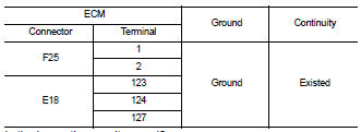
6.CHECK ECM GROUND CIRCUIT
Check the continuity between ECM harness connector and ground.
Is the inspection result normal? YES >> Check intermittent incident. Refer to GI-42, «Intermittent Incident».
NO >> Repair or replace error-detected parts.
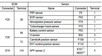
7.CHECK SENSOR POWER SUPPLY CIRCUIT
1. Turn ignition switch OFF.
2. Disconnect ECM harness connectors and each sensor harness connectors 3. Check harness connector for short to power and short to ground, between the following terminals.
*1: CVT models
*2: RHD with M/T models
Is the inspection result normal? YES >> Perform the trouble diagnosis for power supply circuit.
NO >> Repair or replace error-detected parts.
For M/T models : Component Inspection
1. Remove G sensor. Refer to TM-282, «Exploded View».
2. Reconnect all harness connectors disconnected.
3. Place the G sensor on a flat table.
4. Turn ignition switch ON.
5. Select �G SENSOR� in �DATA MONITOR� mode of �ENGINE� using CONSULT-III to check indications according to the following conditions:
: Direction of gravitational
force
*: Check that voltage rises as the G sensor measurement condition changes in the order of (A), (B), and (C).
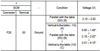
1. Remove G sensor. Refer to TM-282, «Exploded View».
2. Reconnect all harness connectors disconnected.
3. Place the G sensor on a flat table.
4. Turn ignition switch ON.
5. Check the voltage between ECM harness connector terminal and ground.
: Direction of gravitational
force
*: Check that voltage rises as the G sensor measurement condition changes in the order of (A), (B), and (C).
Is the inspection result normal? YES >> INSPECTION END
NO >> Replace G sensor. Refer to TM-282, «Exploded View».
P158A ECM
DTC Logic *: Since this DTC is detected when G sensor calibration is incomplete, there is not replacement parts. 1.PRECONDITIONING If DTC Confirmation Procedure has been previously conducted, .
Except for M/T models
Except for M/T models : Description ECM receives a G sensor signal from TCM via CAN communication to switch combustion for the direct injection gasoline system. For the direct injection gasoline s .
Other materials:
Additional service when replacing ECM
Description When replacing ECM, this procedure must be performed. Work Procedure 1.PERFORM INITIALIZATION OF NATS SYSTEM AND REGISTRATION OF ALL NATS IGNITION KEY IDS Refer to SEC-50, «BCM : Special Repair Requirement» (With intelligent key system), SEC-190, «BCM : Work Proce .
U1000 can comm circuit
Description CAN (Controller Area Network) is a serial communication line for real time application. It is an on-vehicle multiplex communication line with high data communication speed and excellent malfunction detection ability. Many electronic control units are equipped onto a vehicle, and .
Fuel pressure
Work Procedure FUEL PRESSURE RELEASE With CONSULT-III 1. Turn ignition switch ON. 2. Perform �FUEL PRESSURE RELEASE� in �WORK SUPPORT� mode of �ENGINE� using CONSULT-III. 3. Start engine. 4. After engine stalls, crank it two or three times to release all fuel pressure. 5. Turn ignition s .
G sensor nissan juke
Nissan Juke Service and Repair Manual : P1585 G sensor
Description
� G sensor is installed to floor under instrument lower cover.
� G sensor detects longitudinal G and inclination that affects the vehicle and outputs to ECM using analog voltage.
ECM converts the analog voltage value to digital signal and transmits the signal to TCM via CAN communication.
� TCM detects longitudinal G and inclination of the vehicle using information of CAN communication.
DTC CONFIRMATION PROCEDURE
CAUTION:
Always drive vehicle at a safe speed.
Immediately after performing any �DTC CONFIRMATION PROCEDURE�, always turn ignition switch OFF.
Then wait at least 10 seconds before performing the next test.
2.PERFORM DTC CONFIRMATION PROCEDURE
2. Select �Data Monitor� in �TRANSMISSION�.
4. Using the �D� position, increase vehicle speed in constant acceleration within 5 seconds.
5. Select �Self Diagnostic Results� in �TRANSMISSION�.
Is �P1585� detected? YES >> Go to TM-236, «Diagnosis Procedure».
Diagnosis Procedure
1.CHECK G SENSOR SIGNAL
1. Park vehicle on level surface.
2. Turn ignition switch ON.
3. Select �Data Monitor� in �TRANSMISSION�.
5. Check display of �G SEN SLOPE�.
Is the inspection result normal? YES >> GO TO 6.
2.CHECK G SENSOR POWER SOURCE
1. Turn ignition switch OFF.
2. Disconnect G sensor connector.
3. Turn ignition switch ON.
4. Check voltage between G sensor vehicle side harness connector terminal and ground.
Is the inspection result normal? YES >> GO TO 3.
3.CHECK HARNESS BETWEEN TCM AND G SENSOR (PART 1)
1. Turn ignition switch OFF.
2. Disconnect TCM connectors.
3. Check continuity between TCM vehicle side harness connector terminals and G sensor vehicle side harness connector terminals.
Is the inspection result normal? YES >> GO TO 4.
NO >> Repair or replace damaged parts.
4.CHECK HARNESS BETWEEN TCM AND G SENSOR (PART 2)
Check continuity between TCM vehicle side harness connector terminals and ground.
Is the inspection result normal? YES >> GO TO 5.
NO >> Repair or replace damaged parts.
1. Remove G sensor. Refer to TM-282, «Removal and Installation».
2. Reconnect all the connectors.
3. Turn ignition switch ON.
4. Check voltage between TCM connector terminal and ground.
: Direction of gravitational
force
Is the inspection result normal? YES >> GO TO 6.
NO >> Replace G sensor. Refer to TM-282, «Removal and Installation».
1. Install G sensor. Refer to TM-282, «Removal and Installation».
2. Select �Self Diagnostic Results� in �TRANSMISSION�.
4. Perform �G SENSOR REMOVAL/INSTALLATION AND REPLACEMENT�. Refer to TM-182, «Description».
Is calibration complete normally? YES >> INSPECTION END
NO >> Check intermittent incident. Refer to GI-42, «Intermittent Incident».
7.CHECK HARNESS BETWEEN TCM AND G SENSOR (SENSOR POWER CIRCUIT) (PART 1)
1. Turn ignition switch OFF.
2. Disconnect TCM connectors.
3. Check continuity between TCM vehicle side harness connector terminal and G sensor vehicle side harness connector terminal.
Is the inspection result normal? YES >> GO TO 8.
NO >> Repair or replace damaged parts.
8.CHECK HARNESS BETWEEN TCM AND G SENSOR (SENSOR POWER CIRCUIT) (PART 2)
Check continuity between TCM vehicle side harness connector terminal and ground.
Is the inspection result normal? YES >> Check intermittent incident. Refer to GI-42, «Intermittent Incident».
NO >> Repair or replace damaged parts.
Special Repair Requirement
1.PERFORM G SENSOR CALIBRATION
Perform �G SENSOR REMOVAL/INSTALLATION AND REPLACEMENT�.
>> Refer to TM-182, «Description».
P0868 transmission fluid pressure
Description The secondary pressure solenoid valve regulates the secondary pressure to suit the driving condition in response to a signal sent from the TCM. DTC Logic DTC DETECTION LOGIC DTC C .
P1701 TCM
Description When the power supply to the TCM is cut OFF, for example because the battery is removed, and the self-diagnosis memory function stops, malfunction is detected. NOTE: Since �P1701� .
Other materials:
Throttle valve closed position learning
Description Throttle Valve Closed Position Learning is a function of ECM to learn the fully closed position of the throttle valve by monitoring the throttle position sensor output signal. It must be performed each time harness connector of electric throttle control actuator or ECM is disconne .
B2098 ignition relay on stuck
Description The ignition relay integrated in IPDM E/R is operated with ignition switch ON signal from the ignition switch. DTC Logic DTC DETECTION LOGIC 1.PERFORM DTC CONFIRMATION PROCEDURE 1. Turn ignition switch ON. 2. Check DTC in �Self Diagnostic Result� mode of �IPDM E/R� using CONSUL .
Front drive shaft
Exploded View LEFT SIDE 1. Circular clip 2. Dust shield 3. Housing assembly 4. Boot band 5. Boot 6. Damper band 7. Dynamic damper 8. Circular clip 9. Joint sub-assembly : Wheel side : Fill NISSAN Genuine grease or equivalent. : Always replace after every disassembly. RIGHT .


