- Passive crossover network explanation
- The active crossover
- Properties of the passive crossover
- Crossover Network for Speakers Circuit Easy Explanation
- Crossover Network
- Crossover Network Example
- How to build a passive crossover network
- How to build a passive crossover – first step
- The circuit board
- Using the 3 way crimp connector
- How to design loudspeakers — video courses
- Acoustics 101 : Speaker design basics and enclosure design
- Acoustics 201 : Loudspeaker measurements
- Loudspeaker engineering : How to design speaker crossovers
- Placing the components on the board
- Soldering things up
- Finishing touches
- Conclusion
- References
Passive crossover network explanation
Before we get deep into the passive crossover design, let’s start by splitting the crossover network into 2 kinds : active crossovers and passive crossovers . A crossover, regardless of its kind, will take the signal and split it into different frequency intervals or bands, and each band is routed to the appropriate speaker. For example : if you have a 2 way speaker, the crossover will route the low frequencies to the woofer and the high frequencies the the tweeter. See Fig 1 for an example of a 2 way crossover. Same applies if you have a 3 way or more system. The crossover will split the signal into as many bands as there are speakers. More speakers, means shorter intervals, and each speaker works with a narrower frequency range, thus a little less effort on each driver, for a multi-way setup.
- Passive crossover means that the signal is split after it is amplified by the amplifier. For this reason, it has to deal with large currents and voltages.
- Active crossover means that the signal is split before it reaches the amplifier. Which means the crossover works with a low level signal, but for each driver of the system a separate amplifier channel is needed.
The active crossover
It has many advantages versus the passive crossover, but it is more complex to build and requires more amplifier channels to drive the system. While the passive crossover has fewer components, it is more difficult to design. There is more to it than just splitting frequencies. The crossovers need to correct some frequency response imbalances of the drivers, the roll-off slopes need to be on point, so that the transition between low and high frequencies, at the crossover point, is done as flat as possible, with no response dips or peaks, phase corrections etc. Nevertheless, a crossover will make or break a high quality speaker.
Here is a graphical explanation of the active and passive crossovers :
For the rest of this article we will focus on the passive network. Although it has its disadvantages, it is more convenient and more widespread.
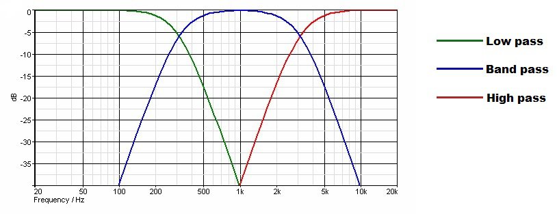
Depending on the frequency it filters, the crossovers are split into 3 categories :
- High pass filter : Filters the low frequencies and lets the high frequencies pass. Used for tweeters
- Band pass filter : Filters some low frequencies and some high frequencies. Used for midrange drivers.
- Low pass filter : Filters the high frequencies and lets the low frequencies pass. Used for woofers.
Properties of the passive crossover
The passive crossover is a circuit board on which you will find capacitors, inductors and resistors. The main characteristics of a crossover network is its inductance (L) and capacitance (C). The inductance and capacitance are frequency dependent, and on different frequencies, they provide a different AC resistance or reactance :
- Capacitive reactance is inversely proportional to frequency => Capacitors provide more AC resistance as frequency lowers
- Inductive reactance is directly proportional to frequency => Inductors provide more AC resistance as frequency increases
Crossover Network for Speakers Circuit Easy Explanation
This application is used as a coupling that couples the audio amplifier to speakers.
Crossover Network
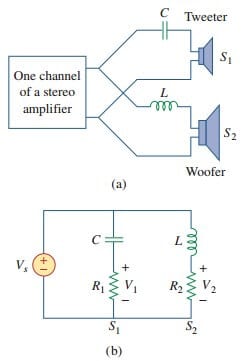
Another typical application of filters is the crossover network that couples an audio amplifier to woofer and tweeter speakers, as shown in Figure.(1a). The network basically consists of one highpass RC filter and one lowpass RL filter.
It routes frequencies higher than a prescribed crossover frequency f c to the tweeter (high-frequency loudspeaker) and frequencies below f c into the woofer(low-frequency loudspeaker).
These loudspeakers have been designed to accommodate certain frequency responses. A woofer is a low-frequency loudspeaker designed to reproduce the lower part of the frequency range, up to about 3 kHz.
A tweeter can reproduce audio frequencies from about 3 kHz to about 20 kHz. The two speaker types can be combined to reproduce the entire audio range of interest and provide the optimum in frequency response.
By replacing the amplifier with a voltage source, the approximate equivalent circuit of the crossover network is shown in Figure.(1b), where the loudspeakers are modelled by resistors. As a highpass filter, the transfer function V 1 /V s is given by
Similarly, the transfer function of the lowpass filter is given by
The values of R 1 , R 2 , L , and C may be selected such that the two filters have the same cutoff frequency, known as the crossover frequency , as shown in Figure.(2).
The principle behind this crossover is also used in the resonant circuit for a TV receiver, where it is necessary to separate the video and audio bands of RF carrier frequencies.
The lower-frequency band (picture information in the range from about 30 Hz to about 4 MHz) is channelled into the receiver’s video amplifier, while the high-frequency band (sound information around 4.5 MHz) is channelled to the receiver’s sound amplifier.
Crossover Network Example
In the network of Figure.(1), suppose each speaker acts as a 6-Ω resistance. Find C and L if the crossover frequency is 2.5 kHz.
Solution:
For the highpass filter,
For the lowpass filter,
How to build a passive crossover network
We’ve designed a crossover before, now it’s time to learn how to build a passive crossover. There are different techniques to building a passive crossover network. Some are basic, some are more advanced and more clean looking. However, I’m going for the middle ground. I mix soldering, crimping, gluing, zipping to make the filter look clean, but at the same time, easy to make.
I’m not going to show you, how the crossover is designed. If you are interested in that, you maybe want to take a look at :
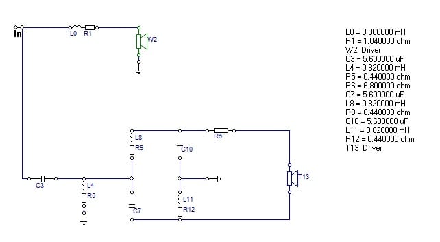
Now that we got that out of the way, here is the schematic for the crossover we are going to build :
This is a 2nd order Linkwitz Riley filter. Actually, it’s an asymmetrical filter, with a first order slope for the woofer and a 2nd order slope for the tweeter. The tweeter also has a ladder delay network and an attenuation resistor.
How to build a passive crossover – first step
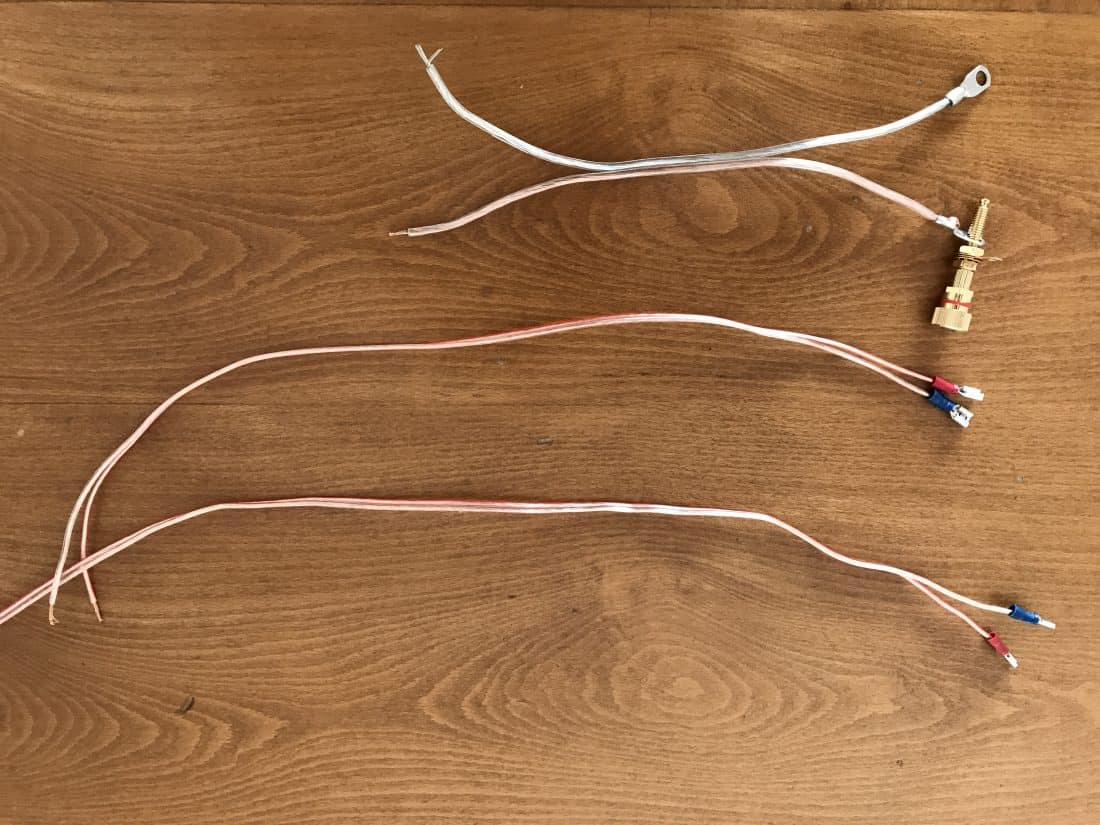
The first step I like to take is to make the cables for the speakers and binding posts.
I try to use thick cables, as thick as the crimp connector allows. Use appropriate crimp connectors for you binding posts (Amazon affiliate paid link). This should be a short cable. In fact all the cables should be as short as possible. I trimmed them after I took this picture. But the cables for the mid-bass should be a bit longer, and for those I used 6.3 mm spade crimp terminals. (middle row). Tweeter cables should also be a bit longer (for reaching purposes) and use 2.8 mm spade crimp terminals for these. Leave the other ends of the cables stripped for further processing.
The circuit board
First thing to do is to get a board to fit the components of the filter. Easiest thing to do is to use a thin piece of wood. However, even easier than this, is to get a piece of MDF that you used to make the enclosure. It’s a bit thick, but it will do. I like to glue 4 small legs to the board. This is because I use zip ties to fix some of the components. The board needs to be of sufficient size to accommodate the components. However, it also needs to be small enough to fit through the mid-bass hole. This board is 14 cm x 15 cm.
Remember, this is my view on how to build a passive crossover. I like to use zip ties on the inductors, and hide the ends of the zip-ties on the bottom of the board. Never use screws to fix the coils, it will alter the inductor value. Some have a plastic casing with a hole in the middle, and the first instinct is to drill a screw in the middle. In conclusion, don’t use metal fixing solutions for the inductors.
Using the 3 way crimp connector
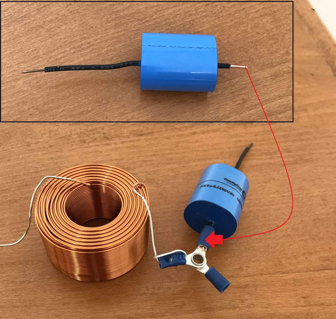
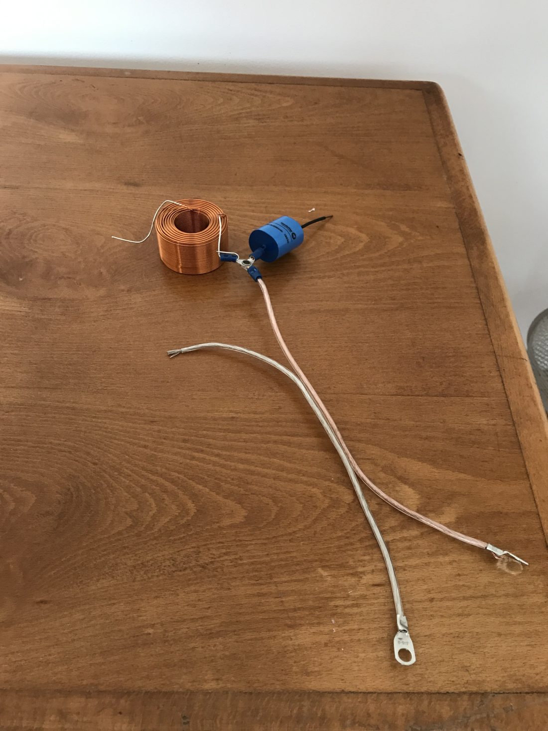
I like to start with the biggest component, usually the inductor on the mid-bass side (L0). In our case the 3.3 mH one. I place it near a corner and work my way from there, so I don’t waste space. If you look at the circuit schematic, you will see that this inductor is connected to the positive input (amplifier +) and the tweeter section of the filter which begins with capacitor C3.
How to design loudspeakers — video courses
Acoustics 101 : Speaker design basics and enclosure design
Acoustics 201 : Loudspeaker measurements
Loudspeaker engineering : How to design speaker crossovers
As a result, I like to use a 3 way crimp connector. This makes it easy to connect 3 components in one spot, using a crimping tool (Amazon affiliate paid link). Furthermore, I can screw it to the board using a small screw. I use a 3 mm drill bit to make holes for both the screws and for passing the zip ties.
Trim one end of the capacitor and crimp it to the connector. Crimp the inductor to the connector also. For the 3rd end of the connector, crimp the positive lead that goes to the positive speaker terminal (the mid-bass).
Placing the components on the board
Here is a pic after I placed some components, and let’s see how to build a passive crossover :
Comments on the above picture :
- Inductors are fastened to the board using zip ties. If the inductor is placed close to the edge, I drill only one hole and route the zip ties along the side of the board. Otherwise, drill two holes.
- Try to alternate inductor positioning. You see that one is placed flat and one is upright. This minimizes influences between the fields they generate. This is a good practice, but sometimes cramped spaces forces you to place inductors close to each other in positions that are not recommended. If so, the inductor values will change slightly. However, if the measured end result is good, you’re good. Here is a chart with ideal inductor placement.
- I used a screw to fix the 3 way connector to the board. This keeps the look clean and fixes the wires closer to the board.
- In the middle, I placed a small ground bar. This is a very convenient place, because whenever you will see a ground icon on the circuit schematic, you will connect it here. Usually, there are several ground connections in any passive crossover build. As a result, being in close proximity to all of the components is a wise choice.
Soldering things up
As much as I love to crimp, sometimes soldering is best. You didn’t think you will learn how to build a passive crossover and avoid the soldering iron (Amazon affiliate paid link), did you? Before we get into soldering, let’s focus our attention to the circuit schematic. You see a lot of lines, which represent wires. However, you have to imagine that there are no wires. You could use cables, but they are redundant, make the design look cluttered and affect the overall resistance of the circuit.
In conclusion, if you look closely at C3, L4, L8 and C7, if your take away the wires, they all converge into a single point. So what I did is, took all the ends of these components, bunch them up in a nice bouquet, twist them with a pair of pliers, and solder everything up.
The same thing I did for the L8, C10, R6. Here, you can easily see on the circuit diagram that they converge into one spot. Connect the rest of the components in a similar fashion.
Where I connect the speaker positive wires (for both the mid-bass and the tweeter), I prefer the usage for crimp connectors. This way I can glue it to the board. As a result, if you pull this wire when attaching / detaching the speaker, it will encounter some resistance. Otherwise, you might pull out the nearest component.
Finishing touches
I always leave the soldering for last. Besides, the 2 obvious bunched up components, there is another spot where I used the soldering iron. Some of the components didn’t have enough length in the wires to reach the ground bar. Usually, I use the screws from the ground bar to fasten the wires mechanically, but they were too short. For this reason, I soldered a couple of components on the top of the ground bar.
Last thing to do is to use some glue for the parts which aren’t fixed to the board. Therefore, I applied glue just beneath every capacitor, the resistor and the pink crimping connectors.
Conclusion
Now you know how to build passive a crossover. At least, you have an idea on how I personally do it. Some like to stick the components directly on the back of the box, some use actual PCB’s. You can go as fancy or as modest as your comfort level dictates.


